Learn about voltmeters and how you can build a series of voltmeters to increase the efficiency of your I/O readings.
Having the correct tools on your electronics workbench can make all the difference to the success of your projects. The DIY Tools Series shows you how you can create some of the most commonly-used tools. In this article, I'll show you how to build what I like to call a voltamatrix — a circuit containing a series of voltmeters (in this case, eight) that can provide many different readings at once.
Check out the other articles in the DIY Tools Series below:
The Importance of Voltmeters
Voltmeters are incredibly important in electronics as they allow a maker to see the potential difference between two points. While multimeters provide power and flexibility they are often clumsy and only provide one voltage reading at a time. To increase the voltmeter's effectiveness, you can create a voltamatrix.
Required Hardware for the Voltamatrix
- 8 x 3-wire voltmeters
- 11 x 1N5817 Diodes
- 4 x LM358
- 8 x 10K Resistor
- 1 x 10 Pin Header
- Stripboard
- Optional: 3D printer for making a face
Voltamatrix Schematic
How Voltmeters Work Together and Voltamatrix Construction Considerations
Voltmeters are not simple to design and require a microcontroller to encode an analog voltage into a digital number which is then shown on a display. While you could design a circuit from scratch, it's much easier to use a premade voltmeter module.
Voltmeter modules come in two varieties: two-wire and three-wire. Two-wire modules only have two wires, power and ground, and the voltage displayed on the voltmeter is whatever the voltage powering the voltmeter is. However, these are not helpful in our project as they have a minimum input voltage (typically 3V), which means any voltage lower than that cannot be seen.
Three-wire voltmeters have three wires: power, ground, and input. These voltmeters can read voltages between 0V and 30V thanks to the separated input, making them ideal for our project. Considering that they only cost a few dollars each (compared to about $10 for a single multimeter), we can cheaply make a device (the voltameter!) that can probe multiple points at once and tell us the different voltages.
These voltmeters, however, cannot read negative voltages and may even be damaged if a negative voltage is attempted to be read. Therefore we need to protect them from negative voltages. The easiest way to do that is to use a series diode between each input and its associated voltmeter.
However, using a series diode between each input would cause two problems:
- The diode forward drop would not allow readings of voltages below 0.6V
- All readings will be off by 0.6V
To fix this, we can use a precision rectifier to protect the voltmeters from negative voltages. A precision rectifier is a special circuit that consists of a diode, an op-amp, and a resistor. The op-amp is configured as a unity-gain buffer with the output connected to the negative input of the op-amp but instead of having a direct connection it is connected through a diode.
The op-amp in the precision rectifier is arranged in a closed-loop (whereby the negative input has a connection to the output). As a result, the op-amp will adjust its output so that the negative input matches the positive input.
To understand how this circuit works its best to start off with everything in the circuit set at 0V. Initially, a voltage of 0.3V is probed at the input and the negative input is read as 0V since the diode is not conducting. This imbalance between the positive and negative results in the output of the op-amp to increase until D1 begins to conduct.
When the negative voltage reads as 0.3V the output of the op-amp remains stable and the output of the precision rectifier matches the input. What makes this circuit interesting is that the output of the op-amp is always 0.6V greater than the input but the output of the precision rectifier is the output of the op-amp minus 0.6V (due to the diode).
There is, however, one drawback to using this precision rectifier with our voltmeters. The voltmeters can read voltages up to 30V even when powered from a 5V source, but our precision rectifier cannot output voltages greater than its power supply. Therefore, we need to power our voltamatrix with the voltage supply of the circuit under test to guarantee that we can read any voltage that may be present. For example, if our circuit under test has a maximum voltage of 25V then our voltamatrix should be powered with 25V.
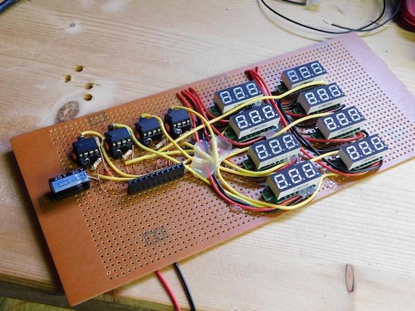
How to Construct the Voltmeters into a Voltamatrix
This project was built on a stripboard since a PCB would have been overkill and the voltmeter modules were directly glued onto the stripboard. The stripboard used was a 20 x 10cm type that is widely available in online stores.
Conveniently, this type of stripboard contains power buses to help reduce the number of wires needed. On reflection, it would have been neater to put all the wiring on the underside of the board instead of the top layer. With the exception of the voltmeter module wires, a thin solderable magnetic wire was used to provide a solderable insulating sheath (no need to strip wires).
Initially, my intention was to make a 3D-printed front cover, but it turns out that while I am a competent electronic engineer my mechanical engineering skills leave much to be desired. Because of this I have decided not to enclose this project and keep the circuit open. However, below are images of my attempt at 3D printing a front cover to demonstrate what this project could look like if designed by a 3D printing pro.