Learn the ins and outs of schematic design for custom PCB art badges. In this series, we're creating a Maker Pro robot!
The mechanical design of the Maker Pro robot PCB badge is complete but we haven't done any of the traditional work involved in developing a PCB by creating the actual electronic schematic.
If you are just starting out with Eagle, there are several getting started tutorials you can read to learn the basics of using the software. In this tutorial, we will just cover a bill of materials for the project and an overview of the schematic design.
Bill of Materials
You will need the following parts to build your Maker Pro robot PCB badge:
Maker Pro Robot Badge Schematic Overview
The schematic design for the Maker Pro robot PCB involves two major subsystems:
- The eInk display that will be used to display QR codes linking to articles on the Maker Pro website.
- The collection of LEDs around the board.
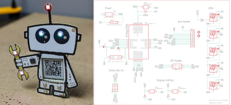
The full Maker Pro robot PCB badge schematic.
The entire board is controlled by an ATmega328p microcontroller. This is the same microcontroller used in the Arduino Uno. Power comes from a pair of AAA batteries.
Now let's take a look at each section of the full schematic.
Power System
Since the Maker Pro robot PCB badge is a portable device, designed to be worn on a lanyard at a conference, it will be powered by batteries.
The power system of the schematic.
A pair of AAA batteries are held in place by a battery clip on the back of the badge. Each of the batteries delivers 1.5V. The batteries are wired in series, so the pair delivers 3V to run the system.
eInk Display
The primary functionality of the Maker Pro PCB badge is to display a QR code on an eInk display located in the center of the badge.
The QR code can be scanned with a smartphone to open articles on the Maker Pro website. The display itself is a 1.54” monochrome eInk display from Adafruit.
The eInk header portion of the schematic.
The display connects to the controller via SPI. Therefore, three pins are used to allow communication between the ATmega328p and the eInk display, a clock line, data line, and select line.
The same SPI interface is used to control the eInk display as well as the onboard SRAM chip and SD card reader, both of which are used to store image data to be shown on the display.
Display Controls
On each of the robot’s legs is a button. These two buttons are used to change the QR code shown on the eInk display.
The display controls in the schematic.
LEDs
As is traditional for PCB art, the Maker Pro robot badge features a collection of LEDs. The LEDs used in the design are WS2812b RGB LEDs with onboard controllers, also known as Neopixels. These LEDs are all controlled from one pin on the ATmega328p but each is individually addressable.
The LED portion of the schematic.
The robot has one LED on the top of the antenna, one on each of the eyes, and two on the wrench in the robot’s hand.
Schematic Review
The electrical schematic for the Maker Pro robot PCB badge is not a complex one. The system is run by an ATmega328p microcontroller. Five LEDs add necessary blinkiness to the design. The most noticeable feature on the schematic is an eInk module that will be used to display QR codes linking to Maker Pro articles.
Download the Maker Pro Robot PCB Schematic
In the next part of this series, we will work on arranging all the components in this schematic around the Maker Pro robot PCB.