Learn how to transform vector drawings into a file Autodesk Eagle can use to design custom PCB art!
Now that we have a vector drawing representing the outline of the Maker Pro robot PCB, we need to move the graphic from Adobe Illustrator to Autodesk Eagle.
To accomplish this move, we start by exporting the drawing from Illustrator in a format that Eagle can understand: DXF. However, there is a bit of prep work to do first.
DXF Files and Eagle
Before we dive in, it’s very important to understand how Autodesk Eagle reads DXF files. Eagle will only recognize straight lines in DXF files. Right now, all the lines in the Illustrator graphic are curves, because this is how Illustrator normally works. Before we export the image, we need to convert all the curved lines into a whole bunch of straight lines that approximate a curve.
If you select the vector outline in Illustrator, you will notice a bunch of points along the lines. These are anchor points. When we convert the graphic to use only straight lines, it will just draw straight lines between these points like connect-the-dots. This will obviously result in an outline that looks quite different than the Maker Pro logo. So, before performing the conversion to use only straight lines, we must add a bunch of additional anchor points.
Adding Anchor Points in Illustrator
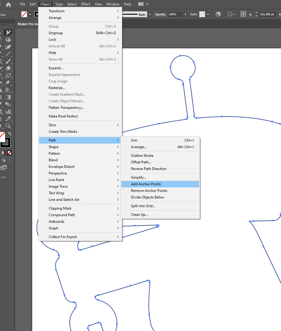
With the outline selected, click Object —> Path —> Add Anchor Points.
Where to navigate to add anchor points.
You will notice more anchor points appear on the outline. Then, repeat that command one or two more times until there are enough anchor points to get a good approximation of the more tightly curved areas of the drawing. Don’t go crazy with the anchor points because later on, when we import the outline into Eagle, Eagle will freeze under the demand of importing a highly complex file.
Now we can set the path to use only straight lines without getting a blocky outline. Go to Object > Path > Simplify.
How to navigate to “Simplify.”
In the dialog box, select Straight Lines.
Select Straight Lines in Simplify.
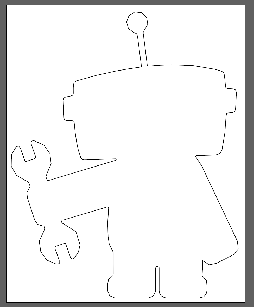
When you press OK, the outline will convert into a series of straight lines that look similar to the curved original version. Because we added so many anchor points, the outline made from only straight lines will approximate the one made from curved lines.
Exporting the Graphic From Illustrator
At last, we can export the graphic from Illustrator so that in a moment it can be imported into Autodesk Eagle. To export the graphic, go to File > Export > Export As.
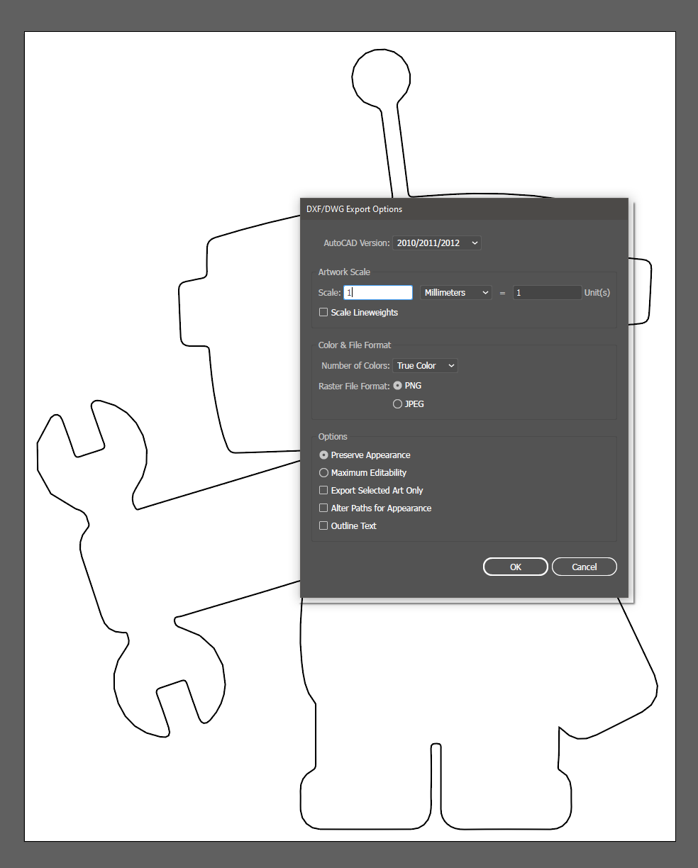
The export dialog box looks a lot like the Save As dialog box. In the file type dropdown, select AutoCAD Interchange File (*.DXF) and click the Export button. In the DWG/DXF Export Options dialog box, there is a section for adjusting scaling in the exported file. In the unit dropdown box, select Millimeters. Then, in the first dialog box, enter 1. Then click the OK button.
Our selected export options.
Importing the Image to Eagle
Now, jump over to Autodesk Eagle and create a new board file. To import the DXF file, go to File > Import > DXF…
How to navigate to Import in Eagle.
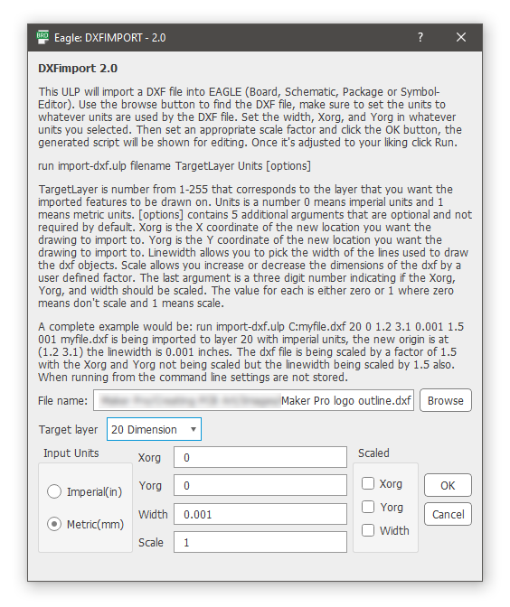
The first thing to do in the import dialog box is to use the Browse button and find the DXF file you just exported from Illustrator. Then make sure that the Target layer is set to 20 Dimension. Set the Import Units to Metric(mm). Finally, click the OK button to import the file.
Our selections for image import.
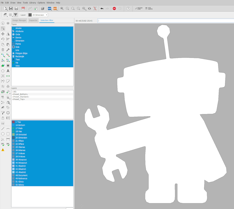
Eagle will then draw the Dimension layer based on your DXF. Depending on the complexity of the design and how many anchor points you added to it earlier, this process could take a couple of minutes.
The dimension layer Eagle drew based on our imported image.
Thus far, we’ve managed to use Adobe Illustrator to trace the outline of a reference image and create a vector drawing. Then we exported this vector drawing as a DXF file which we imported into Autodesk Eagle as the outline layer for the PCB.
In the next part of this series, we will use a similar technique to translate the internal design elements of the reference image — like the black outline, eyes, wrench, and other features — into the PCB design.