Get familiar with Tinkercad, a free design program that allows you to create custom 3D enclosures for your projects.
I think every maker’s been there: you finally finish that project you’ve been working on for so long. Everything is functioning just fine, but yet you feel like something is missing and then it hits you: a custom case! But how do you create an enclosure that not only looks good but also protects the precious circuitry?
More often than not, pre-made project enclosures won’t quite do the job. That is where this guide to Tinkercad will come in handy! It will teach you how to design and manufacture a custom case that looks great and will protect your project for many years without requiring any knowledge of complicated CAD software.
In this article, I'll cover how to create a new account, basic commands, and how to build, add, rotate, and scale shapes and cutouts.
What is Tinkercad?
Tinkercad is a browser-based 3D design and modeling program created to provide a way for a variety of users (beginners to experts) to create projects.
Conventional CAD software options are not only expensive, but they’re also often quite complicated to learn. These programs often have many features, that you won’t even use for something as simple as a custom case. While they are great for professional users, makers will more likely be happy with Tinkercad, which I regularly use. It’s not only free but also very easy to learn and to use.
Getting Started
Before you start designing your case in Tinkercad, make sure to get a rough idea of what you want your case to look like by creating a hand-drawn sketch.
After you have a drawing you are satisfied with, visit Tinkercad's website. You’ll need to create a free account to access the service. After logging in, you’ll be greeted with a screen similar to this one:
A screenshot of Tinkercad's profile homepage.
Click on “Create new design” right below “My recent designs” next to your profile picture. A new design will open up.
Tinkercad Basics
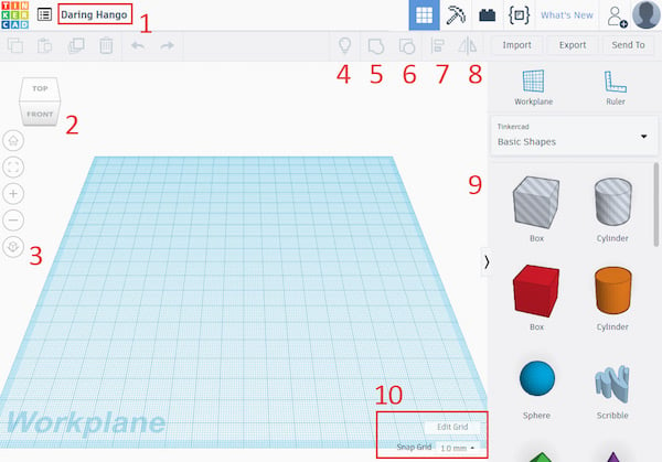
Let’s quickly go over some basics of the main user interface:
- You can change your project’s name here.
- This is the “view cube“. It allows you to rotate the camera or to switch to a side or top view.
- These buttons can also be used to control the camera. From the top to the bottom: return the camera to the default position and orientation, place the camera in a way, that all your objects fit in the view, zoom in and out and switch between perspective and orthographic projection.
- You can hide elements from your scene by selecting them with your mouse and then using Ctrl + H. This button makes all hidden elements visible again.
- Button number five can be used to group objects. Grouping shapes allows you to combine them to a single shape and to create cut-outs and holes. This represents the boolean “union” operation in Tinkercad. You can also use Ctrl + G for this operation.
- This button can be used to split up a previously defined group of shapes. You can also use Ctrl + Shift + G instead.
- Button number seven can be used to align objects.
- This last button allows you to mirror a shape in your scene.
- These are your basic shapes. You use them to create more complex shapes by creating cutouts and combining them into larger and more complex objects.
- You can change the grid with the tools in this area.
Building Shapes
Almost all objects can be built by combining the few basic shapes available in Tinkercad and creating cut-outs. Let’s start with a simple one as an example. Select a cube from the right-hand side of the window and place it on the workplane:
Select the cube shape from the menu on the left-hand side.
After placing the shape on the workplane, a properties window shows up (highlighted with a green rectangle). The sliders in this window might differ from shape to shape, but in this case, you can adjust the dimensions of the red cube and also set a radius and steps (these two sliders will let you create bevels around all the shape's edges).
Right above the sliders, you’ll find two buttons which allow you to change the color of the shape and also define whether it’s supposed to be a cut-out.
Moving, Rotating, and Scaling
You can move the cube on the X and Y axis by dragging it around with your mouse. You can lock the translation to one axis by holding down shift. To move the cube up and down use the small cone, marked with the number four in the image above.
There are different ways to scale a shape. The first one is using the sliders, described earlier. However, I would not recommend doing so, because this option is rather imprecise.
The second method is using the white squares, located at the corners of the shape (see number one in the figure above), to drag the cube and change its size. Use the black squares to scale it in one direction only.
I recommend using the third method, which is to directly input the desired length of a side, by clicking on the label, highlighted with the number two in the image above. These labels appear, when you hover a white square in the corner of a shape. To prevent these labels from disappearing, click on the square you are hovering with your mouse. Using the direct input method will allow you to enter the new length of a side and it’s the most precise way of resizing your shapes.
To rotate a shape, use the curved double-arrows for each axis respectively. One of the double-arrows is marked with the number three in the image above. As before, a label appears when you hover one of those arrows with your mouse. Click on the double arrow to prevent the label from disappearing again.
Creating Cutouts and Holes
If you want to create a cut-out, place a new shape on the workplane and make it intersect the cube where you would like the cut-out to be. See the image below:
Create a hole by placing a new cutout shape on your existing shape.
You can see that I changed the color of the second shape, a cylinder in this case, from a solid color to “Hole”. This will tell the program that this shape defines a cut-out in another shape.
To create a hole, select both shapes and hit Ctrl + G (or use the group-button on the top of the window).
You can always un-join objects with Ctrl + Shift + G (or by clicking the button in the menu bar above the work-pane) and you can then easily adjust the size, shape and position of the hole.
Anyway, the order, in which you join shapes together, matters. Let’s take these three shapes as an example:
If I join the white surface and the cylinder together and then join the result with the red cube, the resulting shape looks like this:
If I, however, group the red cube and the white cylinder together and then join it with the white surface, I get the following result:
By selecting all three and grouping them at the same time, the result looks like this:
Keep this in mind when creating your custom shapes. You should also make sure that the shapes you define as holes are not too complex. You should only use the basic shapes, or the text shape, for creating cut-outs. Cutouts that are too complex can often not be calculated properly and will result in unexpected behavior.
Precise Positioning With the Align Tool
One last important tool that I’d like to discuss is the align-function. You can only access it after selecting two or more shapes on your workplane. The button in the top menu bar will then become available. After clicking the button, you get presented with something like this:
The align tool in Tinkercad.
The black circles mark the corners and the center of each axis. These are the anchor points for aligning the selected shapes. The center one, for example, will align the shapes in the center of the axis. The orange outlines show where your shapes will be positioned after aligning them.
You can display the preview by hovering a circle with your mouse cursor. Click the circle and your shapes will be repositioned. When you are done, click anywhere outside of the selected shapes to close the tool.