Use the ATmega168, an AVR microcontroller, to explore the basics of digital I/O pins and useful bit manipulations.
In the previous article, we looked at how to use a simple cheap USB programmer, the USBasp, with Atmel Studio 7 and WinAVR to program ATmega devices. In this article, we will learn more about ATmega chips as well as the basics of I/O pins.
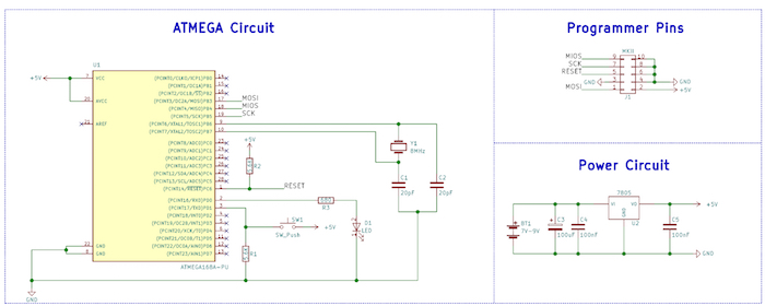
Schematic
The AVR Core
At the heart of most ATmega devices is the AVR CPU, which is described as a RISC-type CPU. However, despite being a RISC CPU, the AVR core is arguably very powerful and has many advantages over competitor devices (such as the Microchip PIC range).
For example, the AVR core contains generic 8-bit registers that can be paired to create 16-bit pointers for memory locations. Also, the AVR core has over 130 instructions, many of which are single-cycle (thanks to the one level pipeline), and there is no banking scheme.
However, AVR devices are particularly prone to bricking when users start to play with the fuses (specific chip options), which is why it is highly recommended that you have multiple AVR devices on hand. Another issue with AVR devices is their difficulty in chip programming (as compared to the PICKIT3 for example) if an official programmer is not purchased.
Despite this, the AVR has become one of the most popular microcontrollers available thanks to the invention of the Arduino, which contains an ATmega at its heart. In fact, an Arduino is just an AVR microcontroller with some special boot loading code and a USB-to-serial converter.
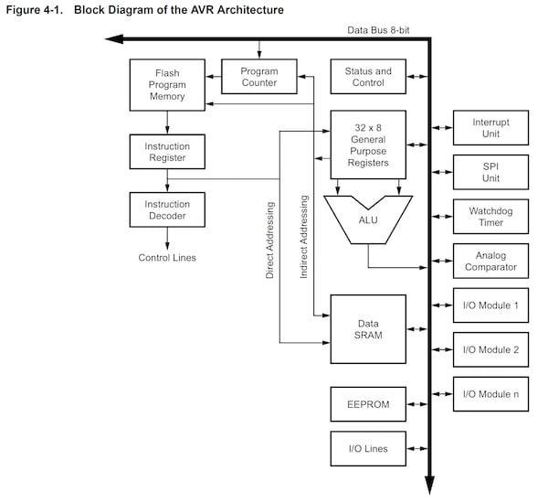
Below is the internal architecture of a typical ATmega device (in our case, the ATmega168).
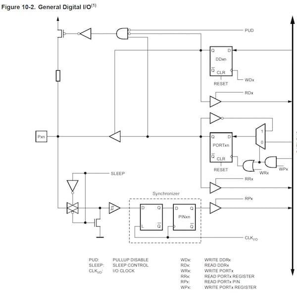
I/O Ports
Knowing a bit about the internal workings of a microcontroller is good, but knowing how to make that chip talk to the outside world is great. Most microcontrollers, if not all, contain pins that allow the device to both read and write digital values to external circuits. For example, an LED could be connected to an I/O (with a series resistor), which would allow the microcontroller to turn the LED on and off. Another example would be a switch, which could be connected between the pin and power, and the microcontroller could perform an action when it detects that the switch has been pressed.
Of course, the microcontroller could be connected to just about any circuit and interact with it in any way that you could possibly imagine. But to do this, we need to learn how I/O ports work on AVR devices and how to use them properly!
I/O ports contain three registers:
- DDRx – Data Direction Register for port x
- PINx – Read from Port x
- PORTx – Write to Port x
Data Direction Register
The data direction register (DDR) is most likely the first register that you configure since the DDR register determines if pins on a specific port are inputs or outputs. The DDR register is 8 bits long and each bit corresponds to a pin on that I/O port.
For example, the first bit (bit 0) of DDRB will determine if PB0 is an input or output, while the last bit (bit 7) will determine if PB7 is an input or output.
In PIC devices, a value of 1 is used for inputs and a value of 0 is used for outputs, but for AVR devices the reverse is true; 1 refers to an output while 0 refers to an input. So let’s say if we want to configure all the pins on PORT B as outputs, we would simply use the following code:
DDRB = 0xFF;
or
DDRB = 0b11111111;
The first example uses hexadecimal, whereas the second uses binary. While it is common practice to use hexadecimal, the binary version can make it more clear which bits in the port are being used as an input or output. If we wanted to turn all the pins on PORT B into input pins then we could use...
DDRB = 0x00;
or
DDRB = 0b00000000;
How about something more complex? Let’s say you want the first two pins to be outputs (PB0 and PB1), and the rest of the pins to be inputs. The following code would do the trick:
DDRB = 0x03;
or
DDRB = 0b00000011;
PINx Register
With our DDR register sorted out, its time to learn how to read digital values into our microcontroller from the real world. This is done using the register PINx where x is the register being read from. Reading from a port is rather easy as shown in the following code example:
dataValue = PINB;
When this is executed, all the pins on PORT B are read into dataValue, and each bit in dataValue will now correspond to the digital levels on each pin at the time the reading was taken. While this is can be useful, we may sometimes want to test individual bits instead of all the bits at the same time. In the PIC, the .bits member could be used to access individual bits, but this is not the case for AVR devices. Instead, accessing individual bits involves a bit of manipulation (pardon the pun), including the use of logical AND, OR, and XOR.
To test if a bit is on (logical 1), the two following statements can be used. These functions perform a logical AND with both the PIN register and the bit (represented as an 8-bit number). If the result is zero, the if statement will not be executed because if statements only execute when the condition is non-zero. The first statement uses a binary value to represent which bit to test, whereas the second statement uses a logical shift instruction to create a bit mask, which represents the bit to be tested. The logical shift version is arguably more readable and thus easier to understand. However, the instruction may take longer to execute than the first (depending on optimization).
if ( PINB & (0b00000001))
or
if ( PINB & (1 << n)) where n = bit under test (0 - 7)
Testing for a logical 0 is easily done by using the negation operator before the main test (!)
if ( !(PINB & (0b00000001)) )
or
if ( !(PINB & (1 << n)) ) where n = bit under test (0 – 7)
PORTx Register
Now that we can read from both entire ports and individual pins, how do we write to ports and individual pins? This is where the PORTx register comes in. Writing to this register (where x represents the port being written to) will result in output pins either being on or off. Remember, the physical output pins will only have digital levels corresponding to the PORTx register IF AND ONLY IF the corresponding DDR bits are set as outputs!
Writing values to ports is very easy:
PORTB = 0xFF;
or
PORTB = 0b11111111;
But what about individual bits? This again is done using bitwise operators and setting/clearing bits is a little more involved. This is because we need to preserve the value of the other bits in the PORT register, otherwise, they may be changed, which could result in unexpected behavior if they are connected to external devices such as LEDs, displays, ICs, etc.
To turn a specific bit on we can use the OR logical operator:
PORTB = PORTB | (0b00000001); Turns on bit 0
or
PORTB = PORTB | (1 << n); Turns on bit n where n = 0 to 7
To turn a specific bit off we use both the AND operator and the NOT operator (~):
PORTB = PORTB & ~(0b00000001); Turns off bit 0
or
PORTB = PORTB & ~(1 << n); Turns off bit n where n = 0 to 7
To toggle a bit (so that it is the opposite to what it used to be) we can use the XOR operator:
PORTB = PORTB ^ (0b00000001); Toggles bit 0
or
PORTB = PORTB ^ (1 << n); Toggles bit n where n = 0 to 7
Pin Names
Using numbers to represent the pins can make for some unreadable code, which is why WinAVR is nice enough to include some definitions we can use instead. See the following examples:
PORTB = PORTB & ~(1 << PINB0); Turns on PB0 (bit 0)
if (PINC & (1 << PINC3)) If statement to test PC3 (bit 3) on Port C
A Simple Example
In our example, we will make a circuit that toggles an LED connected to PD0 when a switch connected to PD1 is pushed.
/*
 * AVR IO.c
 *
 * Created: 03/01/2018 11:25:21
 * Author : RobinLaptop
 */

#define	F_CPU 1000000UL

#include <avr/io.h>
#include <util/delay.h>

int main(void)
{
    // Configure PORT D bit 0 to an output and bit 1 to an input
    DDRD = 0b00000001;

    // Main program loop
    while (1)
    {
		// Wait until the switch found on PIND1 (bit 1)
		if(PIND & (1 << PIND1))
		{
			// Toggle the LED found on PIND0
			PORTD = PORTD ^ (1 << PIND0);

			// Force a delay to prevent de-bounce!
			_delay_ms(100);

			// Wait until the button is released
			while(PIND & (1 << PIND1));
		}
	}
}
Conclusion
Now that we can control I/O pins, there is no reason why we cannot start to use the AVR in projects where a complex controller could be handy. Using the knowledge in this article, you could create a keypad entry system, a complex 7-segment display controller, a music system, or even a basic ’80s-style computer.
Before you go off and start designing your next project, you may want to wait for the next few articles. We will learn how to use the different peripherals that the AVR contains, including timers, controllers, and ADCs!
Cover image courtesy of Microchip.