Maker Pro
Maker Pro

555 timer for a fan

seanspotatobusiness

Sep 11, 2012
193
Joined
Sep 11, 2012
Messages
193
I would like to use a 555 timer to power a fan for ~4-5 minutes when a momentary switch is pressed. I read that the motor should have a flyback diode to protect the circuit - does it matter what the specification of the diode is or will anything work? I read that the 555 chip can source 200 mA and that should be enough for my small fan. Thanks for any help.

0iX6P40.png
 
Last edited:

Harald Kapp

Moderator
Moderator
Nov 17, 2011
13,747
Joined
Nov 17, 2011
Messages
13,747
Almost any diode will work as long as it can withstand the 12 V reverse voltage and the current that is forced through it when conducting.
Use e.g. any of the 1N400x series. Even a 1n4148 will work here.

Regardless of the specs of the 555 I recommend using a transistor buffer stage as explained in our ressource for additional protection of the IC from possible voltage spikes or current surges from the motor.
 

seanspotatobusiness

Sep 11, 2012
193
Joined
Sep 11, 2012
Messages
193
Thanks. I added the transistor. Do you know whether value of the non-timing capacitor on 555 chip pin 5 matters much? I've read that 10 nF is appropriate and I happen to have one that seems to be 30 nF. I figure it's not critical, so long as it's at least 10 nF but I'm not certain.

eAfweal.png
 

Bluejets

Oct 5, 2014
6,942
Joined
Oct 5, 2014
Messages
6,942
Normally it's 0.1uF.
If you are working from a battery it probably won't matter much in the circuit you have there.

Try to keep circuit as a circuit drawing rather than "as built"...makes it difficult to follow, not so much for this but others may get more complex.
Also normally the transistor goes emitter/ground and collector to the motor with the other side of the motor to the 12v rail.

Have a look here where you will find more info than you'll ever need.
http://www.talkingelectronics.com/te_interactive_index.html
Scroll the left side to the 50 555 circuits and click on the book, then scroll the main page.
 

seanspotatobusiness

Sep 11, 2012
193
Joined
Sep 11, 2012
Messages
193
Thanks for your help. I've moved the transistor but I also have another problem in that the talkingelectronics website says the 555 timer chip uses 10 mA while running which means it will be draining the battery during the periods where the fan is off. I'm trying to figure out a way to make the 555 timer chip disconnect itself from the power when the delay runs out and is reconnected when the button is pressed.

I've found this circuit: https://electronics.stackexchange.c...ing-555-to-disconnect-itself-from-electricity which is supposed to do this but I can't figure out how to add those transistors to my own circuit because their switch is connecting reset and Vcc to positive while mine is connecting trigger to GND. Maybe I can use the same concept though if I also use the switch to connect pin 1 to GND (currently it's connected directly in my circuit).

Edit: no, I don't think it's possible to connect both GND and TRIG to ground via the same switch in such a way the GND remains connected to ground (through that PNP/NPN thing) and TRIG disconnects from ground when the button is released.

PnVWL.png
 
Last edited:

Bluejets

Oct 5, 2014
6,942
Joined
Oct 5, 2014
Messages
6,942
Problem with what you are trying to do is you need power on the 555 to make the trigger work.

There may be a settling time for the initiate of the 555 also.

A microcontroller on the other hand can be put to sleep where it draws very little current but you need to know how to program it. Not difficult but takes some studying. Arduino is a good beginning.

Other approach would be get a bigger battery or run your 555 off a plug pack.
LiPo pack might be an alternative for you.( high capacity versus size and weight)

Clipsal used to make a pneumatic switch (air bleed adjustable) probably only $60-$70 these days.

Edit:- another idea may be to use a "touch plate" located beside your push button with appropriate circuit to send power to the 555.
Gets complex very quickly.....
 
Last edited:

seanspotatobusiness

Sep 11, 2012
193
Joined
Sep 11, 2012
Messages
193
This is the final circuit offered on Stack Exchange. Do you think it wouldn't work? I'm still trying to get my head around it.

xj6kDFf.png


The button needs to provide power and activate the trigger at the same time.
 

Bluejets

Oct 5, 2014
6,942
Joined
Oct 5, 2014
Messages
6,942
Yes well, I'm no expert, plenty here are though.
From what you show in the link most say, won't work.
Why don't you simply use a cmos version of the 555..... ????
Have to be super carful with static until it's in circuit but.........
drag out a spec sheet and see.
 

AnalogKid

Jun 10, 2015
2,896
Joined
Jun 10, 2015
Messages
2,896
I also have another problem in that the talkingelectronics website says the 555 timer chip uses 10 mA while running which means it will be draining the battery during the periods where the fan is off.
Change to a CMOS 555 - LMC555. 98% less idle current.

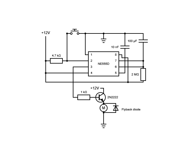
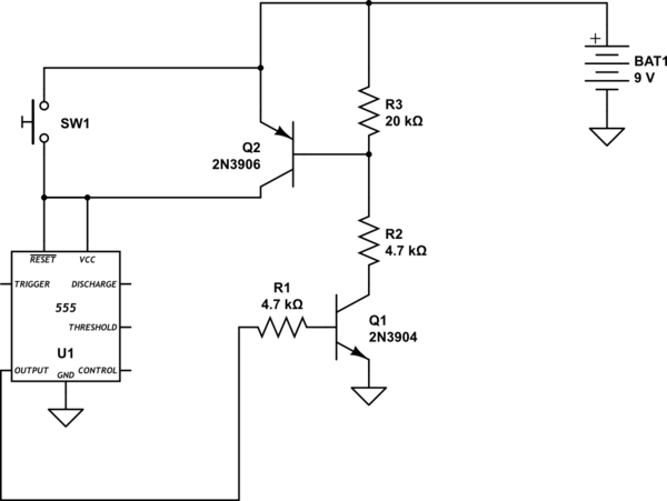
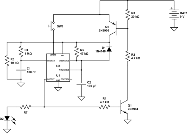
The circuit in post #8 seems overly complex. I suggest going back to post #3, configure the output transistor as a saturated switch as in Q1 in post #6, with the fan in the collector to Vcc. With the CMOS 555, off-state energy is about 0.1 A-h per month at 12 V, less at 9 V.

For extra low idle current, drop the 555 and change to a CMOS CD4093 quad NAND gate. Normally this would be a bit less accurate and repeatable timing period, but your charging current is so low that the timing capacitor's leakage current becomes a measurable error. This is a common problem for any multi-minute R-C timer circuit. Of the 4 gates in one 4093 package, two form the monostable and one inverts the output to drive the external fan driver transistor. Change that to a small power MOSFET to eliminate the base resistor and base current for even better battery life (every little bit ...).

What is the operating current rating of your fan at 9 V?

ak
 
Last edited:

seanspotatobusiness

Sep 11, 2012
193
Joined
Sep 11, 2012
Messages
193
I switched to a supply of 5 V when I found a 5 V fan. The voltage coming out of the 555 output is 3.5 V and I figured a 300 ohm resistor would give at least 10 mA which should which at 40 hfe should give 400 mA. My fan only needs 180 mA but the voltage across the transistor is 2.7 V so the fan only has enough voltage to spin if I give it a flick. It's a 2N2222. I'll try maybe 150 ohms at the base instead but I really think 300 ohm should have been okay?

Changing to 150 ohms enabled the fan to start on its own but it's still only getting about half the voltage with the transistor taking 2.67 V across the collector and emitter.

I found this 555 timer at my local maker space with the intention of swapping it with a CMOS version when I got them but my multimeter says it is using <1 mA when the fan is idle.
 
Last edited:

Bluejets

Oct 5, 2014
6,942
Joined
Oct 5, 2014
Messages
6,942
Transistor is fine to use but as you've found, bit of fiddling to get it right.
If you simply use a 2n7000 mosfet, put a 220r resistor from pin 3 to the mosfet gate and a 10k from gate to ground. Motor goes Drain to positive rail and Source to ground.
Bump up the 555 supply to 6v and you should be ok.
 

seanspotatobusiness

Sep 11, 2012
193
Joined
Sep 11, 2012
Messages
193
I'm using a cheap module which takes the voltage of a lithium cell and increases it to 5.3 V (it's meant to be 5 V but 5.3 V is what it actually provides) since I have a few of them already. I'm not really happy that the 2N2222 Vce is 2.7 V even after reducing the value of the base resistor to 50 Ω but the fan spins for four minutes and the transistor does not get warm.

BZHmApN.png


I would like to modify the circuit so I can cancel the timer and stop the fan. Should this be done with a momentary connection between reset and ground? Alternatively I could add a switch to change the voltage on the capacitor so it fills up faster, bypassing that 1.9 MΩ resistor?

IhoyMy0.png
 

Bluejets

Oct 5, 2014
6,942
Joined
Oct 5, 2014
Messages
6,942
I would like to modify the circuit so I can cancel the timer and stop the fan. Should this be done with a momentary connection between reset and ground? Alternatively I could add a switch to change the voltage on the capacitor so it fills up faster, bypassing that 1.9 MΩ resistor?

Turn the power off.
 

seanspotatobusiness

Sep 11, 2012
193
Joined
Sep 11, 2012
Messages
193
Can it not be done with a momentary switch? I'd like the circuit to stay on so I can use a single button press to start the fan again.
 
Top