- Joined
- Jan 21, 2010
- Messages
- 25,510
Well why didn't you say this before?
Ummm, quite possibly because until this point I was assuming you wanted an analogue output voltage, not that you wanted to switch a relay.
If you look at your original post there is no mention of wanting to drive a relay, indeed you suggest that you want an output that is the difference of the input voltages.
I was under the assumption that when hooked up as a differential amplifier the 741 op-amp will output the difference between the inputs. If that assumption is correct then what am I doing wrong in my simulation to cause a -2.5V on the 741 output?
Now to your second post.
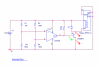
I assume this is what you had in mind?
Closer, but you require a resistor in series with the base of the transistor to convert the voltage output of the op-amp to a current required for the transistor. It is also more usual to connect the emitter to the -12V rail rather than the 0V rail for reasons which you touch on here.
The only question I have is why does my transistor not blow up when there is 10 volt potential difference between the BE junction? In the simulation the only way I can make the transistor blow is to hook up a neg supply rail to the Emitter and ground to the base. Guess I am missing something again...
Firstly, if you connect the -ve supply rail to the emitter, and the base to ground, you are shorting the negative rail to earth via the BE junction. *That* is what will kill the transistor.
-10V on the base compared to the emitter may kill the transistor, a lot depends on the current the comparator can deliver and the individual characteristics of the transistor (it, for instance, may not break down at 10V even though the specs say it will at (say) 8V).
In any case it's not a desirable thing to do to the transistor.
1) Since you now want a comparator rather than an amplifier, you are best looking for a comparator which allows the inputs to go right to the negative supply rail and use a single ended power supply. (beware that the output may be open collector!)
2) The other option is to use a 24V relay and connect the emitter of the transistor to -12V
3) A third option would be to place a diode going from emitter (anode) to base (cathode), which, with the base resistor will eliminate any significant reverse bias on the transistor,
The reason #3, which may seem best, is the last option is that it is a band-aid. Practically speaking it means that if you power this from batteries, the +ve supply will be drained far faster than the -ve supply (so you will be replacing one set of batteries most of the time). If you power it from a purpose built power supply, it will be unnecessarily complex. Even if you went the route of a switch capacitor voltage inverter to provide the -12V rail, the complexity is way higher than it needs to be.
The base resistor you should choose should be one which can provide sufficient base drive (roughly twice the relay current divided by the minimum predicted gain of the transistor) -- probably across 9 or 21V depending on where the emitter is placed.
If the op-amp is replaced with an open collector comparator, this resistance needs to be the total of the base resistor and the pull-up resistor. The presence of a diode to protect the BE junction of the transistor would complicate this somewhat.