Hello,
I would like some help on building an extremely simple current limiting circuit. I would like for the circuit to operate as follows. Input 115-230Vac from mains. The output to the load will be 115-230Vac. The maximum load that can be used is 115Vac - 230Vac at 10watts. If the watts exceeds 10watts, the current limiting circuit will cut off power supply to the load, when the load is removed and the correct load is connected, the power supply will supply the correct load.
Please assist me with this circuit as well as what changes will be requires should I want to change the maximum limit form 10watts to above or bellow.
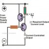
I have provided a circuit that I found on the net but don't know how to use it as I don't know the component required, also if this circuit will work as per my requirements.
Kind regards.
I would like some help on building an extremely simple current limiting circuit. I would like for the circuit to operate as follows. Input 115-230Vac from mains. The output to the load will be 115-230Vac. The maximum load that can be used is 115Vac - 230Vac at 10watts. If the watts exceeds 10watts, the current limiting circuit will cut off power supply to the load, when the load is removed and the correct load is connected, the power supply will supply the correct load.
Please assist me with this circuit as well as what changes will be requires should I want to change the maximum limit form 10watts to above or bellow.
I have provided a circuit that I found on the net but don't know how to use it as I don't know the component required, also if this circuit will work as per my requirements.
Kind regards.
")