Maker Pro
Maker Pro

Adapting PC Headset to Aviation Radio.. ( NEED HELP PLEASE )

(*steve*)

¡sǝpodᴉʇuɐ ǝɥʇ ɹɐǝɥd
Moderator
Jan 21, 2010
25,510
Joined
Jan 21, 2010
Messages
25,510
That was Resqueline, not me :)

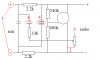
You can't just build this because there are still several unknowns, the values of the capacitors for example. Also I think the diagram is incomplete as we can't see what is below the trimpot.
 

roland_xp_80

May 17, 2011
29
Joined
May 17, 2011
Messages
29
Hi steve and resq,

Ok, as soon as I get home I will open the circuit,

Would that is the only picture that u need to see??

How about the number 3? What do u need for the number 3?
 

(*steve*)

¡sǝpodᴉʇuɐ ǝɥʇ ɹɐǝɥd
Moderator
Jan 21, 2010
25,510
Joined
Jan 21, 2010
Messages
25,510
1) you may need the gain control
2) I looked up the numbers printed on the part, but found nothing. Chances are it's a fairly vanilla jfet though.
3) true, but see 1.

and also

4) we don't know where the ends of that trimpot go yet.
5) this circuit is for an electret element, possibly quite different from what is in the microphone you have.

I have looked (briefly) for schematics of amplifiers operated from the power delivered to an electre mic without success. I have no doubt that something is possible, but I'm not willing to design something from scratch without any sort of test rig .
 

roland_xp_80

May 17, 2011
29
Joined
May 17, 2011
Messages
29
hi thanks for your reply steve,

Appriciate your help, right now I'm out of town, but I will be at my house tonight, and I will then take picture of the circuit board 1 more time without the trimpot, and I will take out the trimpot to get the model number.

Thank you once again for your help..
 

Resqueline

Jul 31, 2009
2,848
Joined
Jul 31, 2009
Messages
2,848
I don't quite think you'll need to remove the trimpot, just look around its legs (and possibly beneath it) to see where the tracks are going.
The resistance value should be printed on its (curved) side.
 

roland_xp_80

May 17, 2011
29
Joined
May 17, 2011
Messages
29
Hi guys, sorry for the rate reply,

this is the photo of the peak.. let me know this image is sufficient.. if not I will take another one..

thanks.. :) appriciate your help..
 

Attachments

  • side1.jpg
    side1.jpg
    89.9 KB · Views: 223

Resqueline

Jul 31, 2009
2,848
Joined
Jul 31, 2009
Messages
2,848
Like Steve stated above, I too believe it's a JFET, not a bipolar transistor.

I'm not quite able to make out where the track from the pot' is going in that picture. How about the other side? Any tracks going from that pin?
 

roland_xp_80

May 17, 2011
29
Joined
May 17, 2011
Messages
29
in the other side is not visible, I have tried to open it, but I do not have specific tools to suck the solder liquid and to pull it out..

Hmm steve or Resqueline if you could create something for me that would be fine, I'm more than willing to try those circuit..

u don't need a rig, I will test it by my self.. I will try to upload the pic again tommorow..
 

roland_xp_80

May 17, 2011
29
Joined
May 17, 2011
Messages
29
The other side is just like the picture I attached.

can u help me to complete the circuit today? I want to buy this components and start building it..

thank you..
 

Attachments

  • other side.jpg
    other side.jpg
    102.8 KB · Views: 187

Resqueline

Jul 31, 2009
2,848
Joined
Jul 31, 2009
Messages
2,848
Can't complete the circuit w/o proper pictures showing the tracks in question..
You have the circuit in hand and it should be an easy task for you to follow the tracks on the PCB, comparing them to the diagram, and so completing it yourself.
As for the capacitor values I'm sure we can make an educated guess based upon the impedances present and common cutoff frequencies.
 

roland_xp_80

May 17, 2011
29
Joined
May 17, 2011
Messages
29
hmm I'm removing this amplifier now, and try it with my PC headset and bring it to fly tommorow.. I will update how does it work..

could you please guess the capacitor values for this circuit and where to put it?

I have no clue of how to read this small chip compared to this circuit. But I will keep trying as we go.. never give up..

thank you very much Resqueline..
 

roland_xp_80

May 17, 2011
29
Joined
May 17, 2011
Messages
29
I have tested above circuit to work(the original) picture.. can u advise what kind resistor should I use in number 3?? and what is number 2??
 

Resqueline

Jul 31, 2009
2,848
Joined
Jul 31, 2009
Messages
2,848
Ok, so if I understand you correctly then the PC headset works with the air-radio when connected via this circuit.

Like I said before, the value of the potentimeter (3) is something you have to read (and tell us). It's written on the curved side of the component,.
And like Steve said before, and I said before, we are unable to dechipher the number on component (2) but believe it to be a completely ordinary JFET (transistor).

Lastly, looking at this picture; surely you are able to see the similarity between the diagram lines and the light green lines on the circuit board, connecting the components.
It should be possible for you to tell where the light green lines from the potentiometer are going. You'll have to do this mental connection if you're to build the circuit anyhow.
 

Attachments

  • circuit combined.JPG
    circuit combined.JPG
    49.6 KB · Views: 357

roland_xp_80

May 17, 2011
29
Joined
May 17, 2011
Messages
29
Correct it does work perfectly..

OK now it does make sense.. :) Just I still have some question,

Based on my latest attachment:
Number 2 is connected there
the potentiometer is Piher Spain.. but there is no information how big is it.
For some reason Number 5 has no leg to anywhere.
I have question what is different between Number 3 and Number 4?

And the JFET 304 transistor, which one is the right one? which you guess, check below:
http://search.digikey.com/scripts/D...dkc_sep&site=us&lang=en&keywords=FDN304PTR-ND

thank you again for all help for you guys..
 

Attachments

  • edit question.png
    edit question.png
    9.4 KB · Views: 232

Resqueline

Jul 31, 2009
2,848
Joined
Jul 31, 2009
Messages
2,848
If there's no labelling on any of the sides of the pot then you have no other option but to measure it with an ohm-meter (measure between pins 2 & 5).
It's quite normal for a pot to have a free connection. It's then termed as a variable resistor.

I'm not quite certain that I have the 680k resistor connected correctly to the transistor in the diagram. You'll have to verify where that track actually goes by measuring too.
Also verify/double-check where pot track #2 ends up.

Capacitor #3 seems to be transferring the signal to the transistor, while #4 seems to decouple the supply to the mike - making the signal appear across the upper 2.2k resistor.
Cap #3 might have a value of 33nF, while cap #4 might have a value of 470nF. The first (unlabelled) cap might have a value of 22nF (or less).

The FDN304 is a P-MOS transistor. I can't tell at the moment if that's what is used there or not, or if it'll work. The diagram actually makes no sense to me as an amplifier.
There's no difference between the three part #s other than packaging and minimum quantity. Choose the middle one (FDN304PCT-ND) if you want to take the chance on it.
 

Attachments

  • circuit side2.jpg
    circuit side2.jpg
    68.9 KB · Views: 216
  • circuit question edit.JPG
    circuit question edit.JPG
    49.5 KB · Views: 257

roland_xp_80

May 17, 2011
29
Joined
May 17, 2011
Messages
29
Ok Resqueline, Thank you for your reply, I will start seeking and let u know the progress. thank you..
 

Manyacarb

Jul 30, 2009
4
Joined
Jul 30, 2009
Messages
4
this is an old post, but Did you guys get this preamplifier work?

I have a very simple one transistor preamplifier that I use in my David Clark headset (not the M-1 dynamic microphone originally installed) and it works pretty well. I will try to post the schematics if anyone is interested.

Thank you :)
 
Last edited by a moderator:

Manyacarb

Jul 30, 2009
4
Joined
Jul 30, 2009
Messages
4
This is the schematic I use on my headset. Basically adapts the electret impedance to a "old" carbon microphone impedance.
If the gain is way too high (in some audio panels/transceivers I noticed that) the second transistor can be omitted. It works really good.
Hope this helps

Regards
 

Attachments

  • PreAmpElectretAviation.pdf
    26.6 KB · Views: 311
Top