Maker Pro
Maker Pro

Basic beginners mistake?

Bruno

Jun 25, 2011
25
Joined
Jun 25, 2011
Messages
25
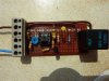
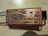
Hi, I know almost nothing about electronics but wanted to control a cooling fan for a car radiator and internet searches turned up a few simple looking circuits, all using NTC thermistors but I have tried building 3 starting with a very basic one based on a single NPN transistor up to one built around a '741' , as in the attached image, but they all do exactly the opposite of what they are supposed to, they all turn off as the temperature rises, so I assume I am making some very basic mistake and would appreciate any advice.
I have been using a 50K potentiometer to simulate the NTC thermistor to speed things up in testing.
 

Attachments

  • temp_alarm.GIF
    temp_alarm.GIF
    6.3 KB · Views: 563
Last edited:

Resqueline

Jul 31, 2009
2,848
Joined
Jul 31, 2009
Messages
2,848
You simply either swap places of the thermistor & the 100k pot, or else the NO & NC contacts of the relay.
 

Attachments

  • temp_alarm.GIF
    temp_alarm.GIF
    6.5 KB · Views: 236

Bruno

Jun 25, 2011
25
Joined
Jun 25, 2011
Messages
25
Tried both, no difference swapping thermistor and pot and if I use the other contact on the relay the fan runs all the time when the ignition is off, even if radiator is cold, wanted it to have power available all the time so it could cool the radiator when the motor was not running if necessary.
 

Resqueline

Jul 31, 2009
2,848
Joined
Jul 31, 2009
Messages
2,848
Ok, with (fused) power straight from the battery then you have to use the NO contact, but swapping places of those two parts will inverse the function. Try again.
 

Bruno

Jun 25, 2011
25
Joined
Jun 25, 2011
Messages
25
Afraid it still only works the relay on rising resistance, have tried checking the circuit several times and I think it is correct but is there some mistake I could have made that would cause it to work the opposite way?
Wondered about connecting it to the sensor for the temperature gauge as I think the resistance on that rises with temperature, it's reading 200 ohms at 18 deg C.
Just found another circuit using 2 transistors connected as a 'schmitt trigger' which looks like I shouldn't be able to mess it up so will also give that a try.
 

duke37

Jan 9, 2011
5,364
Joined
Jan 9, 2011
Messages
5,364
The 270k feedback resistor in your circuit makes it a Schmitt trigger.
If you have a DVM. measure the voltage at the + input, it should be half the supply.
Measure the voltage at the - input and warm up the thermistor and see if the voltage gets to half the supply and from what direction. If it goes away from half the supply then interchange the variable resistor and the thermistor.
Resqueline is right!
Is the problem that you have not set the variable resistor to match the thermistor at the temperature setting that you want.
 

Bruno

Jun 25, 2011
25
Joined
Jun 25, 2011
Messages
25
Voltage from pin 3 to - is 11v, 1v to +, the 2 resistors from it gave strange readings so removed them and they are both around 10.2 K ohms.
I don't really understand the second bit about pin 2 but voltage at pin 2 falls as thermistor heats, to around 1.5 v from +
Have tried adjusting the variable resistor dozens of times but it never seems to make much difference.
Circuit also seemed to stop working toward end of checks and is 'on' all the time now.
 

duke37

Jan 9, 2011
5,364
Joined
Jan 9, 2011
Messages
5,364
You are runnng from 12V so the voltage at the + input (pin 3) should be close to 6V,
The voltage at - input (pin 2) depends on the temperature and will be about 6V at the switching temperature. Set your resistor to get 6V.
 

Bruno

Jun 25, 2011
25
Joined
Jun 25, 2011
Messages
25
Something strange going on, I did a bit of reading about voltage dividers and couldn't understand why I wasn't getting 6v at pin 3 so disconnected the outer ends of the resistors again and they still tested at 10.2 K ohm but I found I was still getting readings from pin 3 to + & - so I removed the 741 and disconnected one end of the 270 K resistor and am still getting a reading of 30 K from pin 3 to - .
I built it on some strip-board and have checked the circuit and layout several times and tested all breaks I have made in the copper strips and also checked for shorts between strips and can't find anything conclusive but I still get the reading between pin 3 and -, I also moved all the resistors so they connected right next to pin 3 and made extra breaks in the copper either side but am still showing 30 K to - !
 

Resqueline

Jul 31, 2009
2,848
Joined
Jul 31, 2009
Messages
2,848
Very strange indeed but I'm sure it's a simple mistake. Are you using the correct pinout? Are you counting the pins the right way around? Show us top & bottom pic's of the layout.
 

Attachments

  • Temp switch.GIF
    Temp switch.GIF
    6.6 KB · Views: 249

Bruno

Jun 25, 2011
25
Joined
Jun 25, 2011
Messages
25
Pics, try not to laugh too much, I expect it doesn't look as good as jobs you guys can turn out.
I was just fitting the holder for the IC, pin 1 is top-left and some of the resistors are still disconnected. Thermistor is not connected, it goes in with the live and to the terminal next to it, it's not clear on the top-view pic but there is a jumper down to pin 2 on the IC. A couple of wire ends look like they are touching other parts on the bottom view but they are just bent at about 45 degrees and there is clearance under them. I did try adding the LED at one point to see if it would tell me if anything else was going on, don't know if I should have removed it.
 

Attachments

  • P1000100 (Small).JPG
    P1000100 (Small).JPG
    60 KB · Views: 199
  • P1000101 (Small).JPG
    P1000101 (Small).JPG
    70.6 KB · Views: 158

Resqueline

Jul 31, 2009
2,848
Joined
Jul 31, 2009
Messages
2,848
Hehe, I've seen worse, it's not half-bad at all, and I'm unable to locate any faults. It should work as it is, though I can't see where the pot is connected.
It's ok with the LED present btw.
So you actually get 11V at pin 3, even with the IC out, but in the beginning it worked?
Double-check if the upper divider resistor is actually 10k (& not 1k). The only other thing I can think of checking is if some of the tracks have a hairline crack.
To verify the circuit I flipped the underside pic upside-down, combined the pics and added the parts. See if I got it all right.
 

Attachments

  • P1000100 (101).JPG
    P1000100 (101).JPG
    82.4 KB · Views: 165
Last edited:

Bruno

Jun 25, 2011
25
Joined
Jun 25, 2011
Messages
25
Your mods to pic for checking look right to me, both resistors are 10 K, don't think I tried checking the voltage at pin 3 with the IC out and don't think I'll get chance tonight.
Very off-topic but can I ask what software you used on the pics, I tried to put them both like that using 'paint' but couldn't get it to work.
 

Resqueline

Jul 31, 2009
2,848
Joined
Jul 31, 2009
Messages
2,848
I used Paint. Select and cut/copy one pic, then open the other and expand the area (drag the small dots on the edge) to accomodate the extra, then paste & flip + move.
 

Bruno

Jun 25, 2011
25
Joined
Jun 25, 2011
Messages
25
Success! I had some time before going to work and re-connected the two 10K resistors but was still getting strange readings and odd voltages at pin 3 with no IC in so checked and rechecked the circuit and back of the board, finally tried scrubbing the back with acetone and a tooth brush and it seems to have fixed it as it appeared to be working properly when I left.
My only concern now is, is it possibly going to be a source of unreliability in the future?
Would it be better constructed on a proper circuit board? A friends father was interested in electronics, but is no longer around unfortunately, and I have been lucky enough to be allowed to use his equipment etc. and from what I can tell he has stuff for making circuit boards but I'd have to do a lot more reading to find out how, I have also found a couple of places doing reasonably priced kits but they then charge double the price of the kit for postage.
The pot in the pic is a bit of a bodge it has one leg bent up and is across pins 2 & 4, I originally had a vertical 100K one in that fitted quite well but I tried the 20K one as I wondered if the other was too high a value.
The version of paint on my PC (Win 7) wont let me do that, the 'paste' command is not available in that situation and if I try to 'drag & drop' it just asks if I want to save the first image before proceeding and whatever I select it just removes the first image before opening the second.
 

Resqueline

Jul 31, 2009
2,848
Joined
Jul 31, 2009
Messages
2,848
Ok, good find. What kind of solder/ flux did you use?
Huh, strange if they've "downgraded" a program, dunno but it seems to confirm my inclination to stay away from the newfangled rubbish/toystuff. I use v. 5.1 for xp.
 

Bruno

Jun 25, 2011
25
Joined
Jun 25, 2011
Messages
25
I discovered another problem when I was trying to set the temperature, if I set the circuit to turn on at 110 C it does not turn off as it cools, after it has cooled I have to turn it off with the pot, ideally I would have liked it to turn off at around 90 C.
Does this mean that I need to be looking for some other method?
Solder is 'Multicore' 5 core alloy solder, it doesn't say anything about the flux in it.
I haven't been using Win 7 for long, only real complaints I have about it are that the 'user account control' is a pain-in-the-bum (though you can turn it off) and the file manager is pretty terrible, I suppose there will be some free software about that will do what this version of paint can't.
 

duke37

Jan 9, 2011
5,364
Joined
Jan 9, 2011
Messages
5,364
You have Schmitt trigger, with feedback via the 270k resistor. This sets the deadband. To get a smaller deadband increase the resistor, try 1M, the deadband will reduce by a factor of about 4.
The Schmitt trigger turns on and off rapidly and doesn't hunt at the control point.
 

Resqueline

Jul 31, 2009
2,848
Joined
Jul 31, 2009
Messages
2,848
Ok, the solder seems to be a good rosin flux electronics type. Some people add acid flux or "solder water" which is bad for electronics - being conductive & corrosive.
Yes, try what duke says (or you can also try to reduce the divider resistor values, down to 1k is acceptable).
You might still have some residual contaminants conducting on your board, affecting the 270k resistance.
Some contaminants are only readily soluble in water so you might want to try to wash it with water first, blow it dry, and then flush with isopropyl alcohol.
Then blow dry with compressed air and leave to dry in a warm place for several hours.
 

Bruno

Jun 25, 2011
25
Joined
Jun 25, 2011
Messages
25
It would appear to be something to do with the solder or related to soldering on the board, after changing to a 1 Mohm resistor the circuit was on all the time again, cleaning (not quite as suggested) got it working but I am still having a problem getting the temperature range I wanted and I wondered if a more sensitive potentiometer might be available, from what I have read a multi-turn type might be better so will try to find one of those and see if it helps.
 
Top