Maker Pro
Maker Pro

Bose wave audio System

Roger_G

Nov 5, 2019
7
Joined
Nov 5, 2019
Messages
7
Hello,
Can anyone help with a schematic for the main board for this Bose system please?
It was purchased in 2010 and I have serial number if anyone can help.
I am trying to repair for an elderly neighbour but struggling.
I have scoured the net with no joy.
Many thanks,
Roger
 

davenn

Moderator
Sep 5, 2009
14,297
Joined
Sep 5, 2009
Messages
14,297
Hello,
Can anyone help with a schematic for the main board for this Bose system please?
It was purchased in 2010 and I have serial number if anyone can help.
I am trying to repair for an elderly neighbour but struggling.
I have scoured the net with no joy.
Many thanks,
Roger

Hi Roger
Welcome :)

can you give a specific model number please, else we have no idea


Dave
 

Roger_G

Nov 5, 2019
7
Joined
Nov 5, 2019
Messages
7
Hi Roger
Welcome :)

can you give a specific model number please, else we have no idea


Dave
Thanks for input Dave.
There is no model number on the unit or the product manual.
The manual is titled Wave Music System.
The serial number is:- 044413391380029AC
It is a CD and AM/FM tuner with the Bose curved front and output power IC is TDA 7376B
At least 3 power rails but don't know what they should be, not regulators, transistor regulated.
All powers up but no supply to 2 off 4052 analog mux de-mux ic's.
Tried to trace out board but tight and I struggled, hence request for circuit diagram.
Bose gave me link to product info not circuit diagram so struggling.
Do you know anyone who may have access to circuit diagram please?
Thanks for the reply,
Rog
 

WHONOES

May 20, 2017
1,217
Joined
May 20, 2017
Messages
1,217
Last edited by a moderator:

Roger_G

Nov 5, 2019
7
Joined
Nov 5, 2019
Messages
7
Try the following link.
I has a number of Bose related publications. Yours may be in there.
https://www.eserviceinfo.com/index.php?what=search2&searchstring=bose+wave+radio

Here is another.
http://www.fixya.com/search/p194741-bose_wave_radio/schematics

And another
http://www.fixya.com/search/p194741-bose_wave_radio/schematics

Plus, there is a DVD available on EBAY that claims to contain exhaustive Bose manuals.
https://www.ebay.com/itm/Ultimate-B...e-manual-510-PDF-manuals-on-DVD-/122038233492

Hopefully there may be the info you require amongst that lot.

I have looked at these with no joy but many thanks for taking the time to reply
 

73's de Edd

Aug 21, 2015
3,640
Joined
Aug 21, 2015
Messages
3,640
Sir Roger_G e e e e e e e e e

From what has been told to me by your post, see if this info fits your unit.
Also I can differentiate even further, by knowing if your back up battery is using 3 cells or a 9 V battery.

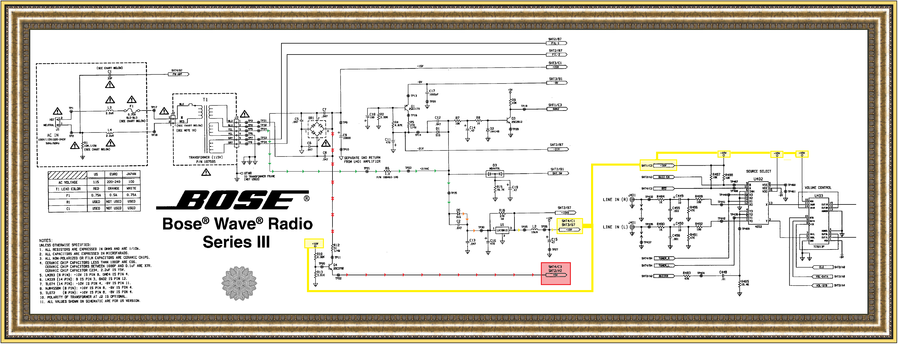
The unit is using a conventional no frills power transformer that generates a basic 15VDC main supply from the BLUE transformer winding, That divides on down to a 5V logic supply BUT is being interlocked with having a +10VDC supply presence.
The 10 VDC supply is derived from the YELLOW transformer winding, as it initially passes as AC down the (GREEN ARROW PATH) until it reaches the DC rectifier diode D5 and transitions out of it as a DC supply . . . . (ORANGE ARROW PATH ) ..
That supply then feeds into the U1 3 term regulator with its 10VDC output as the (YELLOW ARROW PATH ) .

Stop . . . . for an aside observation . . .

That +10VDC supply is also fed aside to initiate the creatig of a +5VDC supply.
It originates at the FWB circuitry of the transformers BLUE winding as a +15 VDC supply and travels down the (DOUBLE RED ARROW PATH) until reaching the collector of pass transistor Q4's collector.
NOTHING happens until your 10VDC supply has come up and created a voltage to divide down at R10 / R13 junction and then having a passage of 5VDC at the emittter of Q4, then its across and down the RED ARROW line to be the switched +5VDC supply leg.

START . . . . . back on the (YELLOW ARROW PATH ) to proceed on the supply path.

Now you mentioned the U402 . . . 4052 signal MUX / selector, so I added it on at the far right side of the schema.
You can then see the +10VDC YELLOW supply feeds of those two CMOS based devices.
Come back, if this info is not in agreement with your unit or for further queries.

Of the 6 WAVE units within our " clan " only one has required service, in the respect of it needing a new AUDIO output POWER AMP I.C. , due to its randomly going off like a LOUD firecracker.

Other supplies are being a minus 21V and minus 5 from D1 from the 21VAC supply line and a dedicated AC winding of ~3-4 VAC from the power transformer GRAY winding for the frontal displays filament.

Thaaaaaaassssssit . . . . .

SCHEMATIC SELECTIVE PORTION REFERENCING . . . . . .
BOSE-WAVE-Series-III-PS-png.png


https://i.ibb.co/mSfthmq/BOSE-WAVE-Series-III-PS-png.png


73's de Edd . . . . .

A girl, with a very enticing and sultry voice, phoned me and said, " I'm at 1211 Elm St. . . . Come on over, there's nobody home."
I hurriedly went right on over.
Nobody was home !

.
 
Last edited by a moderator:

Roger_G

Nov 5, 2019
7
Joined
Nov 5, 2019
Messages
7
Hello de Edd,
Firstly many thanks for taking the trouble to pen this reply, much appreciated.
Working through your points this is what I can say:-
I don' see any batteries but... on the main PCB is a 0.3 Farad 5v5 capacitor so maybe doing the back up instead of batteries?
Transformer is different. Billion no 274813-001 rev 0.4
2 windings 5.8v -0 -5.8v and 1.9v- 0- 1.9 v.
No BR1 bridge rectifier 4 discrete diodes
There is no 10 v 3 terminal regulator but I can see 3 TO220 type power transistors in the power supply area :-
2SC1173
2SA473
KSH210
Power output IC is TDA7376 B
Ref number on main PCB is 291619 - 001
What a shame as that is a great schematic!
Have you come across this before if so .........
Many thanks, I look forward to comments.
Best wishes,
Rog
 

beetle1303

Jun 19, 2023
2
Joined
Jun 19, 2023
Messages
2
Hello de Edd,
Firstly many thanks for taking the trouble to pen this reply, much appreciated.
Working through your points this is what I can say:-
I don' see any batteries but... on the main PCB is a 0.3 Farad 5v5 capacitor so maybe doing the back up instead of batteries?
Transformer is different. Billion no 274813-001 rev 0.4
2 windings 5.8v -0 -5.8v and 1.9v- 0- 1.9 v.
No BR1 bridge rectifier 4 discrete diodes
There is no 10 v 3 terminal regulator but I can see 3 TO220 type power transistors in the power supply area :-
2SC1173
2SA473
KSH210
Power output IC is TDA7376 B
Ref number on main PCB is 291619 - 001
What a shame as that is a great schematic!
Have you come across this before if so .........
Many thanks, I look forward to comments.
Best wishes,
Rog
Hi Roger,
I have just gotten a Bose Wave Music System with identical problem - wondering if you have gotten yours fixed?
 

Roger_G

Nov 5, 2019
7
Joined
Nov 5, 2019
Messages
7
Hi Roger,
I have just gotten a Bose Wave Music System with identical problem - wondering if you have gotten yours fixed?
Hello,
I'm not going to be much use I'm afraid it was a long time ago for my memory....
I did repair it but had to trace the circuitry not so easy.
The PCB I had differed and used discrete transistors not voltage regulators as in Edd's circuit.
It was a transistor if I remember correctly.
I no longer have the circuit diagram that I traced, sorry.
Hope you manage to repair it, let me know,
Best wishes,
Rog
 

beetle1303

Jun 19, 2023
2
Joined
Jun 19, 2023
Messages
2
Hello,
I'm not going to be much use I'm afraid it was a long time ago for my memory....
I did repair it but had to trace the circuitry not so easy.
The PCB I had differed and used discrete transistors not voltage regulators as in Edd's circuit.
It was a transistor if I remember correctly.
I no longer have the circuit diagram that I traced, sorry.
Hope you manage to repair it, let me know,
Best wishes,
Rog
Hi Roger,
Glad that you've fixed it, and a positive news indeed - it's fixable!
Yes, it different board from Edd's but it's the same as yours - 291619-003. I have read from other sources that TL072 (& 2x 4502 MUX) +5vdv are fed from the few transistors near the transformer: 2SA473, 2Sc1173, and KSH210. However, they are all tested good on my board, providing all the required voltages. So must be an open circuit somewhere in between... And yes, the trace is quite impossible...
Still trying.

Thank you,
-Beetle
 
Last edited:

Roger_G

Nov 5, 2019
7
Joined
Nov 5, 2019
Messages
7
Hi Roger,
Glad that you've fixed it, and a positive new indeed - it's fixable!
Yes, it different board from Edd's but it's the same as yours - 291629-003. I have read from other sources that TL072 (& 2x 4502 MUX) +5vdv are fed from the few transistors near the transformer: 2SA473, 2Sc1173, and KSH210. However, they are all tested good on my board, providing all the required voltages. So must be an open circuit somewhere in between... And yes, the trace is quite impossible...
Still trying.

Thank you,
-Beetle
So sorry I can't find the circuit I sketched, but the fault was in that power supply control area for sure.
Good luck it's a good feeling when you find it.
Rog
 
Top