Maker Pro
Maker Pro

capacitor polarity in a phono stage project

(*steve*)

¡sǝpodᴉʇuɐ ǝɥʇ ɹɐǝɥd
Moderator
Jan 21, 2010
25,510
Joined
Jan 21, 2010
Messages
25,510
kinda stabilized on number 6

A reading of 6 from your calibrated finger is close to the maximum temperature you'd expect a transistor to get to and survive. Clearly, cooler would be better. I'd recommend you replace these transistors with something capable of higher current, possibly even a darlington pair.

I would also recommend that you permanently solder those 2k resistors across the power supply output to prevent the voltage rising if there is no load.

Where do you purchase components from? Are they on-line? I'll see if I can pick something out for you.

Alternatively, you could go for the 7805/7905 that I was recommending previously. I can redraw the power supply to show you how to use them.

now the measurments-
R channel
R1 - 0.926v - 12.3mA
R3 - 0.933v - 12.44mA
R8 - 0.366 - 4.88mA
R9 - 1.232v - 16.42mA
L channel
R1 - 0.857v - 11.4mA
R3 - 0.876v - 11.68mA
R8 - 0.371v - 4.94mA
R9 - 1.237v - 16.49mA

as you can see there is a difference between the channels and R8 and R9 are not similar at all. I will check everything for miswiring until your reply

EDIT: seems like I found the miswire. Apparently I didn't understand the schematic correctly. I thought there was a connection between R9 R7 and R6. Resoldering right now.

EDIT: I fixed the mistake. the voltage of R8 and R9 changed to 0.409 and 0.410 respectively (0.404 and 0.405 on the left channel). Plugged it in and... it works! I almost gave up hope!
I am not much of an audiophile but sound is clear enough, there don't seem to be any noises or distortions. the transistors keep getting hot however, I wonder if that could damage them or if that's a normal temperature for transistors to work on.

Clearly I'm not needed here :D Great job!

I still think the power supply needs improvement, if only to keep the transistors from getting so hot.

As an interim measure, you can get some thin aluminium or similar and make a little flag heatsink for these hot transistors. Bend one end into a cylinder that fits snugly over the transistor and use a dot of epoxy glue to make sure it stays put. Obviously make sure the heatsink doesn't touch the leads. No need to make it huge, 1cm tall and with a flag between 1 and 2 cm will be fine. You know it works if the heatsink gets warm in operation. If that seems good enough, you might decide to leave it that way.

The risk is that failure of these transistors could expose your preamp to the full unregulated voltage. Whilst a heatsink for these transistors might be good enough (and they might survive for a long time even without one), I'd hate for want of such a simple modification that a fault took out your entire preamp.
 

giltas

Feb 14, 2014
42
Joined
Feb 14, 2014
Messages
42
I'm usually buying in a local store, Nd if there's stuff I can't get like specific transistors or diodes I order them either from ebay or another online store. If you just tell me what transistors I should look for, I'll find them.
A general question about transistors: How big a difference is there among all transistors (because there are thousands). If I use germanium transistors that I got for a fuzz pedal I once made, would it make the preamp noisy and distorted?

I would prefer just replacing those transistors for now if it is possible, I just don't want to start resoldering everything. If I want to build a new power supply in the future, will you be able to draw for me how to use those 7905 and 7805 regulators?

Finally, if it weren't for you, Steve, I would probably never finish this project! I was so lucky to bump into you and this forum! Otherwise I would probably end up frying everything in my audio system.
 

giltas

Feb 14, 2014
42
Joined
Feb 14, 2014
Messages
42
PS- the electrolytic capacitors I used are of 35v. should I upgrade to 50v to eliminate more noise? There is slight audible noise, especially when there's no audio input that becomes stronger when I put objects or my hand near the exposed circuit (perhaps once I box it up it sounds better)
 

(*steve*)

¡sǝpodᴉʇuɐ ǝɥʇ ɹɐǝɥd
Moderator
Jan 21, 2010
25,510
Joined
Jan 21, 2010
Messages
25,510
I'm usually buying in a local store, Nd if there's stuff I can't get like specific transistors or diodes I order them either from ebay or another online store. If you just tell me what transistors I should look for, I'll find them.

No problems.

I would prefer just replacing those transistors for now if it is possible, I just don't want to start resoldering everything. If I want to build a new power supply in the future, will you be able to draw for me how to use those 7905 and 7805 regulators?

Easy!

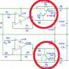
Here's the simple change to stop things heating up. I didn't draw in the 2k2 resistors across the output, but I'd add them too.

Phono PSU alt 1.png

A simple change inside the red circles.

Q1 and Q2 are the original transistors. Q21 is a TIP31, Q2 is a TIP32. Each may be followed by a letter (e.g. TIP32C). These are not at all critical. What you're after is a general purpose medium power NPN and PNP transistor, preferably in a TO-220 package (that is one with a metal tag which will be sufficient heatsinking in this application)

Make sure you know the pinout before you wire them up and test the power supply before you connect it to the preamp. You should expect the ouptut voltage to be about 0.6 volts lower. If you think that will be a problem (I don't) then you can get a 16V zener diode to replace the 15V zener.

Here is the change I suggest for better performance.

Phono PSU alt 2.png

Basically the whole middle bit gets replaced with two simple devices. Again, test before connecting to the preamps. This power supply is technically capable of 1A, but without heatsinks you'll get far less. These chips will actually shut down if they get too how, but at the low currents you're supplying, they're not going to do that.

A general question about transistors: How big a difference is there among all transistors (because there are thousands). If I use germanium transistors that I got for a fuzz pedal I once made, would it make the preamp noisy and distorted?

Germanium transistors are a bi like model T fords. Sure, you can use them, but only very special people think they're better at anything than modern devices. (having said that, germanium transistors are better in high radiation environments and have a higher Vbe reverse breakdown voltage, but in most applications that's like saying that a model T ford is better for drying your hair).

In this application almost every difference between silicon and germanium transistors will be bad. Conversely, in a well designed audio circuit they shouldn't cause any more distortion than a modern transistor.

Finally, if it weren't for you, Steve, I would probably never finish this project! I was so lucky to bump into you and this forum! Otherwise I would probably end up frying everything in my audio system.

Don't sell yourself too short. You've done really well getting to this point.

From the original question, can I presume that this is the first electronic device you've put together with other than trivial components?
 

(*steve*)

¡sǝpodᴉʇuɐ ǝɥʇ ɹɐǝɥd
Moderator
Jan 21, 2010
25,510
Joined
Jan 21, 2010
Messages
25,510
Actually a slight improvement on the second alternative:

Phono PSU alt 2b.png

The diodes across the regulators are a good idea.

You really should use a rectifier diode like a 1N4001 rather than a 1N4148 (and that goes for your current circuit too)
 

giltas

Feb 14, 2014
42
Joined
Feb 14, 2014
Messages
42
Ok so I'll get those 1n4001 diodes and the TIP31 and TIP32 transistors.
The schematic says that the input voltage for the preamp should be 18v, but in reality it turned out to be around 13v. Does that make sense?
If I put the 2k2 resistors, wouldn't it make the output voltage even lower?


And what do you think about my question about the capacitors?
PS- the electrolytic capacitors I used are of 35v. should I upgrade to 50v to eliminate more noise? There is slight audible noise, especially when there's no audio input that becomes stronger when I put objects or my hand near the exposed circuit (perhaps once I box it up it sounds better)

Don't sell yourself too short. You've done really well getting to this point.
From the original question, can I presume that this is the first electronic device you've put together with other than trivial components?

Thank you :)
I have built two effect pedals for my electric guitar but they were fairly easy because I didn't even need to read a schematic for it. There is a website with simple layouts of stripboards with components. http://tagboardeffects.blogspot.co.il/
Needles to say that mistakes are almost impossible with these layouts (take out shorts and dry joints).
 

(*steve*)

¡sǝpodᴉʇuɐ ǝɥʇ ɹɐǝɥd
Moderator
Jan 21, 2010
25,510
Joined
Jan 21, 2010
Messages
25,510
The schematic says that the input voltage for the preamp should be 18v, but in reality it turned out to be around 13v. Does that make sense?

It all comes down to the design of the power supply. The 15V of the zener is reduced by the Vbe (0.6V) of the pass transistor and the series resistors drop it even more.

I'd consider changing the zener to 19V. The voltage will still be under 18V, but not so far under.

If I put the 2k2 resistors, wouldn't it make the output voltage even lower?

Yeah, but that's a problem with the design of the power supply.

And what do you think about my question about the capacitors?

It won't make any significant difference. The power supply is already well filtered. And higher voltage capacitors don't reduce noise any better. I think the power supply's lack of stiffness is more likely to be an issue.

I have built two effect pedals for my electric guitar but they were fairly easy because I didn't even need to read a schematic for it. There is a website with simple layouts of stripboards with components. http://tagboardeffects.blogspot.co.il/
Needles to say that mistakes are almost impossible with these layouts (take out shorts and dry joints).

Yeah, that makes sense.
 

giltas

Feb 14, 2014
42
Joined
Feb 14, 2014
Messages
42
ok, I will make those changes tomorrow as soon as I get the required components.
btw are you from Bremer bay?
 

giltas

Feb 14, 2014
42
Joined
Feb 14, 2014
Messages
42
I got 1N4007 diodes because they didn't have 1N4001's and 18v and 20v zener diodes since they didn't have 19v neither. would that do that job (and which of the zeners is better)?
 

(*steve*)

¡sǝpodᴉʇuɐ ǝɥʇ ɹɐǝɥd
Moderator
Jan 21, 2010
25,510
Joined
Jan 21, 2010
Messages
25,510
ok, I will make those changes tomorrow as soon as I get the required components.
btw are you from Bremer bay?

No, but you show a good grasp of projections. :D

It would take you about 1 tank of fuel to get to my house from there.
 

(*steve*)

¡sǝpodᴉʇuɐ ǝɥʇ ɹɐǝɥd
Moderator
Jan 21, 2010
25,510
Joined
Jan 21, 2010
Messages
25,510
I got 1N4007 diodes because they didn't have 1N4001's and 18v and 20v zener diodes since they didn't have 19v neither. would that do that job (and which of the zeners is better)?

1N4007's are great.

Try the 18V zener first and see what voltage you get (without the preamp connected).
 

(*steve*)

¡sǝpodᴉʇuɐ ǝɥʇ ɹɐǝɥd
Moderator
Jan 21, 2010
25,510
Joined
Jan 21, 2010
Messages
25,510
I've just noticed something potentially very important.

Are you using two OP285's in your power supply (one for each rail) or just one?

If you're using two (and I think I recall you are) then great, because the power supply they're connected to now is beyond their maximum specs.

The absolute maximum power supply voltage is +/- 22V and you have nearly 24V.

It would be best to operate the OP285 for the positive supply from the 0V (use this as it's -ve supply) rail to the unregulated +ve rail. For the -ve supply, use the 0V (as the +ve supply) and the unregulated -ve supply as its power rails. This may have contributed to these chips getting warm, but in any case if that was the only symptom, you've been very fortunate operating them from a supply rail exceeding their absolute maximum ratings.
 

giltas

Feb 14, 2014
42
Joined
Feb 14, 2014
Messages
42
Haha wow! I guess I was lucky to use two. You're really getting me convinced that the design is crappy lol

BTW did you mean to say that Q22 is TIP32? (you wrote "Q2")
 
Last edited:

giltas

Feb 14, 2014
42
Joined
Feb 14, 2014
Messages
42
oh and can I still change the zener diode (I've already changed the OP285's voltage leads as you directed) to the higher voltage one?
 

(*steve*)

¡sǝpodᴉʇuɐ ǝɥʇ ɹɐǝɥd
Moderator
Jan 21, 2010
25,510
Joined
Jan 21, 2010
Messages
25,510
BTW did you mean to say that Q22 is TIP32? (you wrote "Q2")

Yeah, that's correct Q22 is the TIP32.

oh and can I still change the zener diode (I've already changed the OP285's voltage leads as you directed) to the higher voltage one?

Yes, it should bring the voltage up a bit.
 

giltas

Feb 14, 2014
42
Joined
Feb 14, 2014
Messages
42
1N4007's are great.

Try the 18V zener first and see what voltage you get (without the preamp connected).

I tried the 18v and I got around 15.5v across each lead and the 0v (for some reason the positive lead is 0.3v higher). It seemed like I got a little more background noise though, so maybe I will switch back.
However there seems to be another difference. before changing the zener, I had to turn the volume knob about to 7 when nothing was playing to hear the noise (if I did play a record, the volume would be pretty high). Now it seems like I start hearing the noise at volume of 4-5 but then I also get much higher volume then before. Does that make sense?

btw what would be the difference between the 1N4148 and 1N4007?
 
Last edited:

(*steve*)

¡sǝpodᴉʇuɐ ǝɥʇ ɹɐǝɥd
Moderator
Jan 21, 2010
25,510
Joined
Jan 21, 2010
Messages
25,510
I tried the 18v and I got around 15.5v across each lead and the 0v (for some reason the positive lead is 0.3v higher). It seemed like I got a little more background noise though, so maybe I will switch back.

The extra 0.3V is possibly caused by variations in the components. The supply is not actually regulated, so small differences will appear at the output.

However there seems to be another difference. before changing the zener, I had to turn the volume knob about to 7 when nothing was playing to hear the noise (if I did play a record, the volume would be pretty high). Now it seems like I start hearing the noise at volume of 4-5 but then I also get much higher volume then before. Does that make sense?

I'm surprised the circuit is so sensitive to voltage. This actually tells me something else bad about the design, but since the power draw is likely to be fairly consistent, it's not going to be an issue.

btw what would be the difference between the 1N4148 and 1N4007?

These diodes exist solely to prevent discharge of the large filter capacitors going *backwards* through the main pass transistors in the power supply (Q1/11 and Q2/22). They are only doing anything after the power has been switched off. The 1N4148 is a small signal diode designed for to carry a tiny signal. The 1N4007 is a rectifier diode that can carry substantial current. It's a bit like the difference between a pair of ballet pumps and some steel caped boots. There's potentially a lot of power stored up in those capacitors and I'd just feel happier with diodes that won't expire if they are discharged quickly through them.
 

giltas

Feb 14, 2014
42
Joined
Feb 14, 2014
Messages
42
btw the new TIP31/32 transistors also get pretty hot somewhere around 3-4 in the finger calibration.
Oh and should I connect the 0v to the ground of the mains cable?
 

(*steve*)

¡sǝpodᴉʇuɐ ǝɥʇ ɹɐǝɥd
Moderator
Jan 21, 2010
25,510
Joined
Jan 21, 2010
Messages
25,510
btw the new TIP31/32 transistors also get pretty hot somewhere around 3-4 in the finger calibration.

3 to 4 is fine. They are dissipating pretty much the same heat as the smaller transistors, but are a larger package so their temperature rise is smaller.

If you wanted to, you could bolt them to a small heatsink. Here is an example of a very small heatsink. I picked that one because it shows the mounting hardware. In this case the mounting hardware insulates the heatsink electrically from the tab on the transistor (that is connected to the collector). A secondary purpose of this type of insulating washer is to improve thermal contact between the transistor and the heatsink. The alternative is heatsink compound, and that's a little messy. In your case, for such low dissipation, the better thermal contact would not b a huge issue. Better heatsinks will also have one or more legs to allow the heatsink to be attached to your board so as not to place strain on the legs of the transistor.

Oh and should I connect the 0v to the ground of the mains cable?

Your device is mains powered, so any exposed metal parts should be connected to mains earth. Essentially that will mean 0V should be connected to ground. However, beware that this can cause ground loops.
 

giltas

Feb 14, 2014
42
Joined
Feb 14, 2014
Messages
42
I connected the 0v to mains earth and it actually reduced the noise. The preamp sounds pretty good now. All I need now is a new amp and better speakers XD
I wonder if I should start another project. If so, is there any DIY amplifier you recommend? how much harder such a project would be?
oh and I ordered those heatsinks you linked.
BTW there is still some static noise that starts only as soon as I place the needle on the spinning record (when the needle is in the air you can't hear it) so I guess it's coming from the record itself or the turntable rather than the phono preamp. What do you think?
 
Top