Maker Pro
Maker Pro

circuit breaker alarm

Alistair Ballantyne

Nov 16, 2020
36
Joined
Nov 16, 2020
Messages
36
Hello,

I do not see where the wiper of the potmeter is connected.

For better understanding of the layout of a breadboard, have a look at the following picture:
View attachment 63221
Also have a look at the attached PDF.

Bertus
Thanks.
I have connected the wiper potmeter as suggested but still makes no difference.
I didn’t think the wiper always had to be connected but I have probably got that wrong?
The buzzer still continuously sounds and the beam break does nothing.
In your opinion is this a robust design?
 

Attachments

  • IMG_0773.JPG
    IMG_0773.JPG
    242.8 KB · Views: 3

Alistair Ballantyne

Nov 16, 2020
36
Joined
Nov 16, 2020
Messages
36
The #1 schematic shows 1/2 of an LM358 for the opamp, and you mention the LM358 in other posts.

BUT . . .

The opamp in post #16 is a 741, and the wiring is correct for a 741. However, a 741 will not run correctly on 5 V. Per the datasheet, the minimum Vcc is 10 V (or +/-5 V).

The photo also shows a resistor from the inverting input to Vcc. I think I know what you are trying to do here, but the pot wiring is incorrect.

Please post a new schematic.

AND, since no one else has said it - cover the photodiode and see what happens. Probably nothing given the other circuit issues, but . . .

ak
Thanks.
This is a different circuit with the 741 and 9v.
Covering the photodiode makes no difference - but Im confused here - I thought the led transmitter and photodiode needed to see each other to complete the circuit?
 

AnalogKid

Jun 10, 2015
2,925
Joined
Jun 10, 2015
Messages
2,925
A photodiode is not a fully integrated IR receiver; it's just a diode. It sees all ambient light of all frequencies from all sources. If any of it is in the right frequency range, it responds. It is common for a circuit like this to work in a dark room, but fail when the sun comes up because the diode is overpowered by the ambient light. Sorta like why you cannot see stars in the daytime sky. What you want to do will work if the LED transmitter is sufficiently brighter than the room's ambient light *as seen by the diode*. Both the LED and the diode have lenses molded into their bodies, and that helps a lot.

Other photoelectric schemes modulate the IR transmitter with an AC signal or a data stream. The photodiode passes everything to the receiver circuits, which discriminate among various noise and signal patterns, and extract something useful. Those systems are relatively immune to ambient light. Your TV remote control works this way.

Yours does not. That is not automatically a bad thing. Everyone starts here, and learns.

ak
 

Delta Prime

Jul 29, 2020
2,137
Joined
Jul 29, 2020
Messages
2,137
Apologies it seems I offended you.I was not making fun of you. But I believe I added to your frustration, so I'm sorry. The PDF I provided you is a wealth of information that is directly related to what you are trying to achieve. Good luck to you bye-bye.
photo_1711751831278.png

photo_1711751547300.png

photo_1711751725764.png
 

Alistair Ballantyne

Nov 16, 2020
36
Joined
Nov 16, 2020
Messages
36
A photodiode is not a fully integrated IR receiver; it's just a diode. It sees all ambient light of all frequencies from all sources. If any of it is in the right frequency range, it responds. It is common for a circuit like this to work in a dark room, but fail when the sun comes up because the diode is overpowered by the ambient light. Sorta like why you cannot see stars in the daytime sky. What you want to do will work if the LED transmitter is sufficiently brighter than the room's ambient light *as seen by the diode*. Both the LED and the diode have lenses molded into their bodies, and that helps a lot.

Other photoelectric schemes modulate the IR transmitter with an AC signal or a data stream. The photodiode passes everything to the receiver circuits, which discriminate among various noise and signal patterns, and extract something useful. Those systems are relatively immune to ambient light. Your TV remote control works this way.

Yours does not. That is not automatically a bad thing. Everyone starts here, and learns.

ak
That makes a lot of sense and is v useful, thanks.
Having tried three different circuit options I can see it is a waste of time.
But why do people post these things in the first place?
I have just worked my way through 'Electronics for Dummies' and made all the circuits at the end.
No surprise - they all worked perfectly as you would expect.
I will buy a book of instructional circuits I think - at least I know they should be tested and robust.
 

Alistair Ballantyne

Nov 16, 2020
36
Joined
Nov 16, 2020
Messages
36
Apologies it seems I offended you.I was not making fun of you. But I believe I added to your frustration, so I'm sorry. The PDF I provided you is a wealth of information that is directly related to what you are trying to achieve. Good luck to you bye-bye.
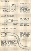
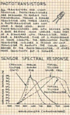
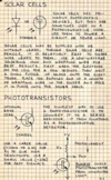
View attachment 63235

View attachment 63236

View attachment 63237
Cool, thanks. Yes indeed the frustration was riding very high!
This information is v useful and certainly adds to the knowledge bank.
Ill try the shield option as a last attempt to see if I can get something working here.
Good input thanks
 

AnalogKid

Jun 10, 2015
2,925
Joined
Jun 10, 2015
Messages
2,925
I will buy a book of instructional circuits I think - at least I know they should be tested and robust.

First, you have discovered a great truth - m-m-m-m-Many of the circuits on the innergoogle are intentional garbage. But there is an alternative.

It is with great trepidation that I do this, because for an undisciplined soul this can be free crack cocaine.


Note that those are just the hobby books. WRH also has tons of heavy-lift books up to the graduate-school level.


Waaaay back, pre-internet by many years, when textbooks were above me and the book selection at the library was ultra-thin, I bootstrapped my electronics education with magazines. Analog and digital circuits, telephony, audio, radio, video, broadcast television, computers, printed circuit board design - whatever, there were cheap hobby mags and free trade mags. When you are done with the books, note that WRH has almost every issue of almost every electronics hobbiest magazine *** in the world ***.

The magazine projects were perfect. Beyond just a plain circuit, they explained what it did, why it did it, how it worked, design trade-offs, each component's function, how to build it, how to package it, how to align it, how to test it, how to use it - total project awareness in a few pages. If you want to learn electronics for free, go through hobby mags from the 60's to the 80's. It's all there in digestible bite-sized articles.


This is just one of several book and magazine archive sites. Don't thank me.

ak
 
Last edited:

danadak

Feb 19, 2021
797
Joined
Feb 19, 2021
Messages
797
A buzzer is typically piezo or magnetic. Drive circuits for both different.
Piezo presents a ton of C to opamp output, which can cause its own
oscillation independent of what you think the OpAmp inputs are doing
due to stray C. In both cases you can get some HV or high current
transients.

Search the net for application notes on driving. Especially if its magnetic
a diode for back emf across it good idea. And I would support the idea
using a transistor buffer to decouple it from OpAmp output. Especially
in case of Piezo.

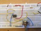
I notice your breadboard shows no bypass cap on OpAmp power
supply. Use a tant, say ~ 10 uF or better, and a .1 uF ceramic.


Regards, Dana.
 

Alistair Ballantyne

Nov 16, 2020
36
Joined
Nov 16, 2020
Messages
36
I'm stuck here.
Want to make a PIR activated alarm using 2N2222A but add a timer delay so can set the alarm but then exit the room before alarm activates.
Tried this:
V1
1715694559065.png

Switch on and delay works but then alarm is activated for time duration before switching off.
It then is inactive until PIR activated.
So only works in part.
Was told "When you power up the PIR, there is a short period where the voltages are settling down, which can lead to false triggering. If you can arrange the PIR to power up as soon as you start the timer, but use the timer output to block the signal to the buzzer until it times out, that should give you what you need."
So tried the following:
V2
1715694939389.png
Buzzer stays on constantly so I have obviously got that wrong.
Any ideas?
Thanks.
 

Bluejets

Oct 5, 2014
7,057
Joined
Oct 5, 2014
Messages
7,057
See the forum covering mains loss alarm........section from Ralph Bacon in particular.
 

AnalogKid

Jun 10, 2015
2,925
Joined
Jun 10, 2015
Messages
2,925
Want to make a PIR activated alarm using 2N2222A but add a timer delay so can set the alarm but then exit the room before alarm activates.

Again, need a lot more information.

PIR device part number / model number / vendor / website - anything?

Voltage and current ratings for the buzzer?

What is the voltage for the circuit?

What is the PIR device output signal when it senses someone - a high voltage level, a low voltage level, an open collector switch to GND - ?

How long of a time delay before the PIR output is stable?

Depending on the answers, this might be doable with just 2 transistors and no 555.

ak
 

Alistair Ballantyne

Nov 16, 2020
36
Joined
Nov 16, 2020
Messages
36
Again, need a lot more information.

PIR device part number / model number / vendor / website - anything?

Voltage and current ratings for the buzzer?

What is the voltage for the circuit?

What is the PIR device output signal when it senses someone - a high voltage level, a low voltage level, an open collector switch to GND - ?

How long of a time delay before the PIR output is stable?

Depending on the answers, this might be doable with just 2 transistors and no 555.

ak
  • 9v battery supply

  • Items bought from UK company - Bitsbox:

  • HC-SR501 PIR Module
  • PIR motion sensor with high/low TTL 3.3V output signal.
    Sensitivity (up to 7m) and output duration (20s - 5min approx.) adjustable.
    5V - 20V DC supply.
    Supplied with a fresnel lens.
    Can be fitted with a LDR to provide inhibit in light function for security light switching

  • Budget Piezo Sounder - Intermittent
  • ST078
  • Built-in oscillator circuit - intermittent tone. Operating voltage: 3-24Vdc. Diameter 30mm

  • How long of a time delay before the PIR output is stable?
  • Not sure how to answer this. When switched on there doesn’t seem to be much delay before the PIR triggers with body movement.

  • Not sure if that helps?
  • Appreciate your time.
 

AnalogKid

Jun 10, 2015
2,925
Joined
Jun 10, 2015
Messages
2,925
Correct me if I'm wrong - the goal is to inhibit the sensor output at power-up, and prevent the beeper from beeping for a few seconds while you leave the room. After that, the sensor controls the beeper without delays - when the sensor "sees" something, the beeper goes off immediately.

Yes / no - ?

ak
 
Last edited:

AnalogKid

Jun 10, 2015
2,925
Joined
Jun 10, 2015
Messages
2,925
add a timer delay so can set the alarm but then exit the room before alarm activates.

How long a delay? The datasheet says the module can take up to 60 seconds after power-on to stabilize.

The sensor output can drive a 2N2222 directly, so what is needed is a circuit to inhibit this for 1 minute, then get out of the way and let the PIR have direct control of the beeper.

First pass, it smells like 1 additional transistor.

ak
 
Last edited:

AnalogKid

Jun 10, 2015
2,925
Joined
Jun 10, 2015
Messages
2,925
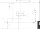
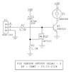
Here is a first pass at a schematic.

The PIR signal at P1pin2 drives Q1 to control the beeper. When power is applied there is 0 V across C1, so the Q2 gate is at 9 V and it pulls the Q1 base to GND no matter the state of the PIR signal. After about 1 minute, C1 has charged up (down?) to around 2 V, and Q2 starts to turn off.This allows the PIR signal to get through to Q1 and drive the beeper.

Q2 is a FET because its gate current almost exactly 0 uA. Compared to a bipolar transistor base current, this allows a much smaller value for C1. In fact, C1 probably should be 33 uF, or even 22 uF

ak

!!PIR-Output-Delay-1-c.gif
 
Top