Maker Pro
Maker Pro

Clean square waves using a 555 timer?

dorke

Jun 20, 2015
2,342
Joined
Jun 20, 2015
Messages
2,342
LTSpice would be fun for that section, but I don't think it can be simply pulled apart from the rest of the circuit.

Looks like when active, Q20 drives the circuits low and activates the discharge transistor, Q14. It also looks like it supplies the collector of Q25. I assume, when the reset pin is energized with positive voltage, the base has sufficient current to pull the gate high and we have voltage between and current flows to the diode in the center of the page.

I doubt I can add much to the thread, so I will leave you with this link that I found invaluable when looking at the 555 for a circuit: http://www.doctronics.co.uk/555.htm

Not very complicated.
Here it is,I have pulled out the output stage(totem-poll and drivers).
We are left with a single input and single output to simulate,feed the input with a square wave at 10KHz or so.
Just use a small signal NPN tr. model like the 2N2222 or 2N3904 etc.
For the diode use a small signal si-diode like the 1N4148

555-output.png
 

CDRIVE

Hauling 10' pipe on a Trek Shift3
May 8, 2012
4,960
Joined
May 8, 2012
Messages
4,960
Chris,
True the 1K limits the current as you say.
But the slopping behavior is entirely due to the series cap.

A voltage drop of 1V(and more )from VCC is normal for the 555,even at relatively low output current of a few mA.
The reason being the output of the 555 isn't rail-to-rail (it is so only for the low output state but not for the high one).
Thus the "difference" between 0 to 8ma is so noticeable .
I must have spent at least 45 minutes struggling over how, exactly, I was going to reply to this. This is because your reply would only make sense if I just fell off the bed of a truck and was absolutely clueless about the relationships between R C in series or parallel circuits. Nor am I unaware of the Bipolar 555's inability to swing high equal to the Vcc rail.

In hopes that there's no mistake... My last post is questioning the 555's Load/ No Load output. When I spice an LM555 I see a mere 20mV drop between no load and a 1KΩ load.

I would like to see a static test with the 555 output held High.
First remove the R2 so there's absolutely no load on the output pin except a DVM.

(1) With no load Pull the Trigger pin low to put the 555 in a static Hi state.
(2) Switch in a 1KΩ load.

What's the load - no load measurements? I would expect no more than 200mV and even that would be a high estimate.

Chris
 

hevans1944

Hop - AC8NS
Jun 21, 2012
4,891
Joined
Jun 21, 2012
Messages
4,891
Still, it all adds up to a big bux investment eventually. I haven't added to my stock of resistors and capacitors lately, except for a onesie-twosie purchase of some polyester dielectric caps for a specific project. So, maybe I will model that 555 output stage in LTSpice AND build a model of the output stage with discrete components so I can look at real voltages with an oscilloscope. Heck, I guess the first step should be to bread-board the 555 as @Xeno Xenox did and see if I can re-produce the spike. We'll see...
 

hevans1944

Hop - AC8NS
Jun 21, 2012
4,891
Joined
Jun 21, 2012
Messages
4,891
What's the load - no load measurements? I would expect no more than 200mV and even that would be a high estimate.
The datasheet graph clearly shows the output is at least 1.3 V less than Vcc at 25 C, in agreement with @dorke's analysis in post #72, and rising to more than 1.6 V at 100 mA load.

upload_2016-4-26_16-11-2.jpeg
 

CDRIVE

Hauling 10' pipe on a Trek Shift3
May 8, 2012
4,960
Joined
May 8, 2012
Messages
4,960
The datasheet graph clearly shows the output is at least 1.3 V less than Vcc at 25 C, in agreement with @dorke's analysis in post #72, and rising to more than 1.6 V at 100 mA load.

View attachment 26477

Hop, the Load / No Load was the only issue I was addressing. Not the fact that the 555 can't swing to the Vcc regardless of source load. My sarcasm in that post seems to still be lost in the Twilight Zone so before I become exasperated I'll let it go.

That said this graph clearly shows ~ 1V drop difference between no load and a 10mA load conditions. Unfortunately my spice simulations don't come close to reproducing this at all.

This does confirm that testing the output unloaded is not a good practice. Loading the output was mentioned in many early replies, including mine.

Chris
 

CDRIVE

Hauling 10' pipe on a Trek Shift3
May 8, 2012
4,960
Joined
May 8, 2012
Messages
4,960
Update:

Tina provides 555 models in both Spice and Spice Macros. I swapped out the pure Spice model with a Spice Macro and Vo now follows that load vs. voltage drop graph closely.

My apologies to Xeno for drifting off of the overshoot issue!

Chris
 

Xeno Xenox

Mar 13, 2016
50
Joined
Mar 13, 2016
Messages
50
@CDRIVE:

If you build my circuit using that SPICE macro, can you recreate the voltage hump at the beginning of the high phase?
 

hevans1944

Hop - AC8NS
Jun 21, 2012
4,891
Joined
Jun 21, 2012
Messages
4,891
Update:

Tina provides 555 models in both Spice and Spice Macros. I swapped out the pure Spice model with a Spice Macro and Vo now follows that load vs. voltage drop graph closely.

My apologies to Xeno for drifting off of the overshoot issue!

Chris
I am sorry that I missed your point. Sarcasm now noted vis a vis R vs RC vs no load on the output.

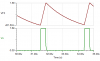
So, in an attempt to simulate the overshoot problem in LTSpice, I joined the LTSpice Yahoo! public forum today and went looking for accurate 555 models. Attached is the first transistor model I found. When run "as is" in LTSpice (as a re-triggered monostable) there are oscillations in the output high state as the timing capacitor approaches a certain level of charge.

I have no idea what the oscillations mean, and have not yet had time to "play" with this particular model. That means I haven't been able to verify the accuracy of this model against "real" circuitry. Also, I am very much a novice in learning to use LTSpice, despite many years of being "exposed" to the technology of Spice simulation. I tend to think along the lines of Bob Pease with regard to SPICE simulation, but am prepared to change as personal computers and SPICE models continue to improve.

Anyway, this particular transistor model is at least a baby step towards simulating, and perhaps understanding, the cause of the overshoot in @Xeno Xenox bread-board circuit. I will continue looking for a better model, and perhaps decimate this one to just the output stage for test purposes, but the "proof" is in the reality of a powered-up real component with real oscilloscope measurements, not in how well a SPICE simulation reproduces that behavior.

OTOH, if I can inject some parasitic inductance and/or capacitance into the model and observe the same overshoot that appears in the "real deal," that will lend some credence to the idea that it is an implementation artifact rather than a deficiency of the 555.

@CDRIVE I looked at TINA several years ago but never used it. LTSpice seems to be the de facto standard for SPICE simulation today, at least in the hobbyist community, and maybe for professional design as well. It may be possible to import TINA SPICE models into LTSpice, so I will look into that too.

Despite some serious misgivings about model accuracy, I like the "look and feel" of LTSpice, so I will probably continue to become more familiar with it... as long as that doesn't cut into the time available for prototyping real circuits.:D

Hop
 

Attachments

  • ne555 transistor level timer.asc
    11.6 KB · Views: 165

CDRIVE

Hauling 10' pipe on a Trek Shift3
May 8, 2012
4,960
Joined
May 8, 2012
Messages
4,960
@CDRIVE:

If you build my circuit using that SPICE macro, can you recreate the voltage hump at the beginning of the high phase?

Sorry to say no. Moreover I wasn't even able to produce a 50% duty cycle. For some odd reason C is charging nearly 3 times faster than it's discharging.

The thread has become long, so to save me time sifting through it please post your most recent schematic so I can reproduce it exactly.

RE Spice Simulations:
To the best of my knowledge all spice flavors are built upon Berkley Spice, originally developed at Berkley University California. Spice models have not always been easy to obtain because manufacturers have not always provided them. This issue is becoming less prevalent but it was the impetus for formation of Spice Forums. These forums also exist because a spice model is only as accurate as the netlist is. If the real device has parasitic inductance but is neglected in the spice model then the simulations won't agree with the real world. That's why those groups spend much of their time creating their own or modifying the models provided by the manufacturers. I read through the Netlist of the Spice Macro I'm using and can safely say that I see no "L" included. The header indicates that the model was provided by Philips Semiconductor.

Hop, do you see any "L" included in the LTSpice model?

Chris
 

Attachments

  • upload_2016-4-28_10-20-28.png
    upload_2016-4-28_10-20-28.png
    6.8 KB · Views: 134

hevans1944

Hop - AC8NS
Jun 21, 2012
4,891
Joined
Jun 21, 2012
Messages
4,891
Hop, do you see any "L" included in the LTSpice model?

The only things in the netlist are transistors, resistors, and a few capacitors that are external to the model. Nary an inductor in sight. There is a library reference to standard BJTs which are used to define two transistor types in the model. I looked at the ASCII lib file in Notebook and saw several hundred BJTs, defined there by Linear Technologies, but I didn't see anything in any of those transistor models that resembled an inductor... but then I am not familiar (yet) with all the parameters they do specify for each transistor. There has to be something to define the frequency response in the list of parameters. I need to do some more research on how transistors are defined in SPICE.

I still have no idea why the output would break into high-frequency oscillations when the timing capacitor reaches a certain voltage level. I have to assume this is an error in the model.

In the model I uploaded in post #91, the TRIGGER input is stimulated with a series of eight pulses. If the capacitor is charged above a certain level, the low-to-high transition of the trigger will reset the output low, otherwise this transition is ignored. The output then remains low until the trigger makes a high-to-low transition, setting the output high and allowing the timing capacitor to charge. If the capacitor charge reaches a level that causes output oscillations, the trigger will still set the output low on the low-to-high trigger transition. The timing is such that there are about two trigger pulses within each capacitor charge/discharge cycle. Low-to-high transitions of the trigger have no effect on the output until the capacitor has charged to a certain voltage level.

The simulation shows eight consecutive trigger pulses. Once the trigger transitions from high-to-low, with the output low as a result of the previous low-to-high trigger transition, the capacitor is allowed to recharge again. The voltage on the capacitor does not terminate the output, whether the output is oscillating or not. The low-to-high transition of the trigger input terminates the output if the capacitor has charged to a sufficiently high voltage, whether this occurs before or after output oscillations begin. After the eighth pulse, the output remains high in an oscillating state with the trigger output low. Presumably, if there were a ninth trigger pulse, the pattern would repeat.

I have not seen this behavior with a real 555 and an external trigger, but that doesn't mean it wouldn't occur. If I can find the time, I will dig out my packed-away electronics stuff and see if I can duplicate this particular model's weird functionality with a real 555 and real resistors, and real capacitors. Might take a little thought to provide a string of suitable pulses though. Probably would need yet another 555 for that!

Hop
 

dorke

Jun 20, 2015
2,342
Joined
Jun 20, 2015
Messages
2,342
I have build this little 555 bugger circuit with an unknown manufacture IC.
Tested it with an analog TEK465B scope ,probe at 10X(a cheap Chinese one...)
The scope isn't good enough for that measurement (BW=100Mhz ),but that's what I have.

The 555 was decoupled with a 15uF tantalum.
Couldn't reproduce "the bump",a "staircase-like" top is evident.

With no load the output high is at 9V(=vcc).
With a 1K load the output high is at 8V.

IMG_1704.jpg img_1705.jpg

Without decoupling, "no bump" either just a strong classical overshoot.

IMG_1706.jpg
 

CDRIVE

Hauling 10' pipe on a Trek Shift3
May 8, 2012
4,960
Joined
May 8, 2012
Messages
4,960
I've been using Spice for quite some time now but I'll readily admit to not being an expert when reading spice code. This link has been a great aid in improving my understanding of it and the various flavors. The most common of which would be PSPICE.
http://www.ecircuitcenter.com/index.htm

As far as LTSpice being the de facto simulator is concerned; that's only true because it's free. The Texas Instruments website thinks enough of Tina to offer a free version of it called TinaTi.

I have three Spice apps on this PC. Tina, LTSpice and PicaxeVSM, which is a limited version of Proteus/Isis, devoted to Picaxe only PICs but includes many other chips and all commonly known discrete devices . Out of the three apps I've found Tina to be about 10x faster when constructing circuits.

One thing I know about Spice (regardless of the provider) is they all find their most difficult task to be simulating oscillators, especially Sinusoidal flavors. My simplistic view on this is that oscillators can be thought of as a condition of instability. :)

***************************************************************
Xeno, where are you? Did Aliens beam you up?

Chris
 

CDRIVE

Hauling 10' pipe on a Trek Shift3
May 8, 2012
4,960
Joined
May 8, 2012
Messages
4,960
Dork, IMHO your scope is plenty good enough to analyze the overshoot issue of this topic. Your decoupling results should be pinned somewhere in the forum! :cool: Talk about the importance of proper decoupling ... WOW! :eek:

Chris
 

hevans1944

Hop - AC8NS
Jun 21, 2012
4,891
Joined
Jun 21, 2012
Messages
4,891
Just for reference, below is a copy of the original waveform with it's overshoot and following "ledge".

upload_2016-3-13_21-47-59-png.25585


The horizontal axis time base is 100.0 ns per major division in the original versus 200 ns per major division in @dorke's hardware "simulation" without an output load and without decoupling of Vcc. As he said, "a strong classical overshoot" indicative of inductance, but in his case strong, virtually critical dampening with only a single oscillatory cycle...
 

CDRIVE

Hauling 10' pipe on a Trek Shift3
May 8, 2012
4,960
Joined
May 8, 2012
Messages
4,960
Since we're going back in time with the early posting of waveforms it may also be worth mentioning that the scope's cal output test (though the breadboard) should be considered totally inconclusive. After all, the Cal output is not injecting any surge current on the Vcc rail as the 555 does at the points of output state transition.

Chris
 

dorke

Jun 20, 2015
2,342
Joined
Jun 20, 2015
Messages
2,342
In memory of Hans Camenzind the inventor of the 555 timer.
I added an entry here.
It is very interesting to hear the voice recordings.

As a final note for this thread ,I would like to repeat one conclusion:

Do not use the #3 pin in a "self generating,RC timing" circuit of the 555.
It will introduce a large timing error and degrade the stability,
use the pins intended for that ,i.e 2=trigger,6= threshold,7=discharge.
 

Xeno Xenox

Mar 13, 2016
50
Joined
Mar 13, 2016
Messages
50
I have build this little 555 bugger circuit with an unknown manufacture IC.
Tested it with an analog TEK465B scope ,probe at 10X(a cheap Chinese one...)
The scope isn't good enough for that measurement (BW=100Mhz ),but that's what I have.

The 555 was decoupled with a 15uF tantalum.
Couldn't reproduce "the bump",a "staircase-like" top is evident.

With no load the output high is at 9V(=vcc).
With a 1K load the output high is at 8V.

View attachment 26526 View attachment 26527

Without decoupling, "no bump" either just a strong classical overshoot.

View attachment 26529

Interesting...

All of the chips I've tested have been labeled as Texas Instruments NE555 chips. Do you know what variation of 555 you used?
 
Top