Maker Pro
Maker Pro

Converting from AA to Li-Ion

eptheta

Dec 20, 2009
188
Joined
Dec 20, 2009
Messages
188
If the batteries are in series to get the required 9V (ish) then you can't easily charge them from a 5V USB charger because the ground connection is likely to be tied directly to the USB ground. This means that you will short the batteries out.
Yeah, I'm aware of that, and I'm going to stay far away from multiple cells until I get a single cell charging and discharging safely first.
I didn't need the whole 9V. I always used 9V batteries and a 5V regulator to bring it down for the uCs (Just because 9V batteries were easier to find-- they really should make 5V batteries). In any case, most devices I care about are happy to work at 3.7V, so multiple cells won't feature just yet.
Even those 433Mhz wireless modules demand a 3-6V supply ! How nice.
 

(*steve*)

¡sǝpodᴉʇuɐ ǝɥʇ ɹɐǝɥd
Moderator
Jan 21, 2010
25,510
Joined
Jan 21, 2010
Messages
25,510
For a single cell, there are numerous chargers designed to run from 5V (actually there are numerous for more than one cell too)

Here is one very simple device.

Note that this device does not terminate the charge after the voltage in the cell reaches the set point. I believe the correct method of charging is to continue at a fixed voltage (and consequently very low current) for a certain time interval before terminating the charge.

Continuing to float them is probably nowhere near as bad as overcharging them with an excessive voltage though.
 

eptheta

Dec 20, 2009
188
Joined
Dec 20, 2009
Messages
188
(TL;DR version in blue)

Again, I am already using one of those ICs (MCP73833) for charging. It's just discharging that I'm trying to work with.

I have a few problems with the + feedback setup that I'd like some help with:
Now, about the positive feedback. I did a few calculations which led me to the optimal resistor values for the setup. 2 problems with that:
1. The voltage gap for the triggering is way too small (3.7V when on, and 4.2V when off)
2. The resistor values I get are too small, and too much current will go waste as a result.

So I did a bit of trial and error, and changed only one resistor value, but I had to sacrifice on triggering the 'on' state. I'll explain my concerns with the
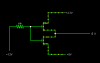
 circuit diagram:
Untitled.png

-The AC source represents the fluctuating (charging and discharging) Li ion battery (it's biased to go from 3V to 5V).
-The battery and switch on the left represent the USB supply.
-I've added a diode to the Li ion supply Because when I plug in the charging chip to USB, I would also want to supply the load, and If I connect the +ve rails together without a diode, the 5V source would pump current through the Li-ion battery and damage it. I'll lose 0.7V though. There's a better way for sure, but I couldn't think of anything else that didn't involve bulky relays.

The +ve feedback has created a band where fluctuations are allowed. (When Vbat reaches 3.7V, the (+) input is pushed down by 0.08V, making sure the output stays LOW even if there is a small rise in voltage due to the load going off.

Here's the problem though:
As the schmitt trigger would, I have a threshold to overcome when the output starts out LOW as well. That happens to be ~4.5V, which my source would never reach.
So, lets say that it's operating happily at around 4V and I decide to switch off the device and switch it on again. When I switch it on, the output starts at LOW, positive feedback increases the voltage gap, and it checks if I have a voltage of 4.5V instead of the usual 3.6V/3.7V to turn on again, which I don't, so it stays off.
I don't need 2 thresholds, just one, but as far as I can see, the feedback imposes the 2nd threshold, which prevents me from switching off and on the device at will.
Also, there's no point in trying to bring the threshold down to 3.7V because then the band gets too narrow and the effect of hysteresis is pretty much negligible.


Anything I can do about this ?

EDIT:Sorry, the link was bad
 
Last edited:

BobK

Jan 5, 2010
7,682
Joined
Jan 5, 2010
Messages
7,682
Show us the circuit. You can adjust the hysteresis of a schmitt trigger.

Bob
 

eptheta

Dec 20, 2009
188
Joined
Dec 20, 2009
Messages
188
̶I̶'̶m̶ ̶b̶e̶g̶i̶n̶n̶i̶n̶g̶ ̶t̶o̶ ̶b̶e̶l̶i̶e̶v̶e̶ ̶t̶h̶a̶t̶ ̶t̶h̶e̶ ̶s̶c̶h̶m̶i̶t̶t̶ ̶t̶r̶i̶g̶g̶e̶r̶ ̶i̶s̶ ̶n̶o̶t̶ ̶r̶e̶a̶l̶l̶y̶ ̶w̶h̶a̶t̶ ̶I̶ ̶n̶e̶e̶d̶.̶ ̶I̶ ̶n̶e̶e̶d̶ ̶s̶o̶m̶e̶ ̶o̶t̶h̶e̶r̶ ̶s̶o̶r̶t̶ ̶o̶f̶ ̶f̶e̶e̶d̶b̶a̶c̶k̶ ̶t̶h̶a̶t̶ ̶w̶o̶r̶k̶s̶ ̶o̶n̶ ̶o̶n̶l̶y̶ ̶o̶n̶e̶ ̶o̶u̶t̶p̶u̶t̶ ̶s̶t̶a̶t̶e̶ ̶a̶n̶d̶ ̶i̶g̶n̶o̶r̶e̶s̶ ̶t̶h̶e̶ ̶o̶t̶h̶e̶r̶.̶

EDIT:
What about this: I keep the two thresholds wherever they are as long as the lower threshold is at 3.7V, and introduce a capacitor or inductor on the op amp inputs.
Say I put a capacitor between ground and the (-) terminal, then when I insert the battery, the capacitor should act as a short for a fraction of time, thus pulling the (-) to ground and producing a high output, which triggers the HIGH starting state on the output.

For some reason, I can't get this to work on the simulator, but it seems to work in my head. Any comments ?
 
Last edited:

eptheta

Dec 20, 2009
188
Joined
Dec 20, 2009
Messages
188
Hi, I successfully added positive feedback and it works like a charm now that I put a capacitor at the non inverting input of the comparator.

I do have another little question though:
When the li-ion battery is charging through the IC (MCP73833), I want to take advantage of the fact that there's the voltage source of the charger(5V USB).
Instead of just charging and simultaneously powering the load, I want to switch over the load to the USB voltage source.

I first thought of doing it by just placing a diode (or more appropriately, a diode and a transistor/mosfet to act as a switch) to prevent a damaging current from flowing through the li-ion battery, but I'd prefer not to lose the 0.7V

Otherwise, I was thinking of using 2 low voltage mosfets arranged to be an spdt equivalent, but I don't know if that's overkill.
attachment.php


So, is there any other way I can accomplish this?
Thanks
 

Attachments

  • Untitled.png
    Untitled.png
    4 KB · Views: 186

khankll

Feb 6, 2011
110
Joined
Feb 6, 2011
Messages
110
sorry for not reading ur last few posts. but u mentioned that only overdischarge is issue.. have u tried the to verify that ur bbatteries do get over discharged as the protection ckt shgould never allow this..?

most liions can be safely discharged to 2.7-3 volts.. i discharge to 2.50 to 3 volts and my battery is still running strong.. it works for 2,5hours at .5A discharge
 

eptheta

Dec 20, 2009
188
Joined
Dec 20, 2009
Messages
188
I thought the protection circuit was the 'air bags' for the battery. That is, it will shut down at some low threshold, but it's better to just pay attention and avert an accident than rely on the airbags to save your life.
Everywhere I read, it was suggested that there be two levels of over-discharge protection, one in-built into the battery pack and one external in your own circuit.
I also read that when the protection circuit kicks in, the battery effectively 'shuts down' and you need to take a little extra effort to get it up and running again, which cannot be achieved by just charging again.

Maybe the rest of your circuit just stops drawing current at 2.5-3V so it seems like the protection circuit kicked it. If you just connect say a resistor to the terminals and let it discharge for a long time, I'm pretty sure it can go lower, but I'm not entirely sure.

Also, since you're here, could you point me to any concrete reference that says that the battery can be safely discharged to 3V ? I can't find a datasheet for the mobile li-ion battery I have, nor can I find a general "one-datasheet-fits-all".

I've seen several forum posts by other people asking for the lower threshold and they get varied responses, some even suggest lower thresholds as high as 3.6V (which is why for now, I'm discharging to 3.6V as well, but I'll lower it when I'm sure of the actual threshold)

Even more evidence comes from my mobile phone itself. When my mobile phone goes off due to low battery, the voltage is around 3.6V. Is this because this is the lower threshold of the battery ? Or can the mobile circuitry not work on anything less ?
 

khankll

Feb 6, 2011
110
Joined
Feb 6, 2011
Messages
110
most mobile phone batteries are Lithium ion.. newer are li polymer..
liion come in variety of physical shapes cylindericall or prismatic..
chemistry is same.. shape is different..

u can have a look at Candle light forums .. in flashlight and batteries included section.. there u will find suitable reports..

https://www.google.com/search?hl=en...f4QSs3rmgDA&ved=0CMwBEK0CMAM&biw=1276&bih=886
those people have good experimental mind...

also kep in mind one fact doesnt stanfds fpr all..
so u can jut test one battery doischarge

u can read data sheets for sanyo,samsung,panasoic liion cells (both prismatic and cylinderical ) at their websitres..

and many companies use their cells just relabeling it..
 

khankll

Feb 6, 2011
110
Joined
Feb 6, 2011
Messages
110
also can u tell me whatmodel of batteries u have ?
their number ?
 

eptheta

Dec 20, 2009
188
Joined
Dec 20, 2009
Messages
188
I googled that before I posted here. That very post "li-ion discharge limit - 2.5v/2.7v/2.8v/3v" was the inconclusive one, which got me confused. I'll let it go down to 3.5V though, that's when the rest of the circuit will stop working anyway.
I have a Nokia BL 5J battery.

Can anyone help with my other question from before ? (About electronic equivalents to SPDT switches without the diode loss)
 

(*steve*)

¡sǝpodᴉʇuɐ ǝɥʇ ɹɐǝɥd
Moderator
Jan 21, 2010
25,510
Joined
Jan 21, 2010
Messages
25,510
(About electronic equivalents to SPDT switches without the diode loss)

mosfet (with low Rds(on)) (that's SPST and polarised, it really depends on the limits of the voltages you're trying to switch and the voltages available to do the switching.)
 
Last edited:

eptheta

Dec 20, 2009
188
Joined
Dec 20, 2009
Messages
188
Well, I have to switch between a 3.6-4.2V source(Li ion) and a 5V source(USB), of which the 5V will provide the switch's input.

I think I'll resort to buying several of these MAX4730 ICs if I find them being sold around here. Unfortunately, I don't know what the 'popular' ICs are for this sort of thing, and where I stay, the guys only stock ICs that are frequently bought.
On top of that, the salespeople only understand model numbers, so asking for "any SPDT CMOS analog switch IC" will get me only looks of confusion. Oh, and they don't keep any sort of catalog.
 

(*steve*)

¡sǝpodᴉʇuɐ ǝɥʇ ɹɐǝɥd
Moderator
Jan 21, 2010
25,510
Joined
Jan 21, 2010
Messages
25,510
3.5 ohms is a pretty high resistance.

I'd be looking at a couple of p channel mosfets that have their gates alternately tied to ground. If the ground does not need to be common, you could use a P and an N channel device and switch the gate from ground to +V
 

eptheta

Dec 20, 2009
188
Joined
Dec 20, 2009
Messages
188
Sorry, but I don't understand your description of the circuit too well.
Could you point me to a circuit diagram?
Thanks.
 

(*steve*)

¡sǝpodᴉʇuɐ ǝɥʇ ɹɐǝɥd
Moderator
Jan 21, 2010
25,510
Joined
Jan 21, 2010
Messages
25,510
This circuit has some problems, but may be useful.

the two alternate power sources are on the left and right.

The output is in the middle.

Hold the control input high to select the right input, low for the left.

If the voltages are dissimilar, the body diode will allow the "turned on" source to charge a lower voltage "turned off" source. You could eliminate this with a diode (shottky preferably) in series with the lower voltage source.

There are circuits using 2 mosfets which can eliminate this problem, but driving them is a little more tricky.
 

Attachments

  • Scan-120606-0001.jpg
    Scan-120606-0001.jpg
    9.6 KB · Views: 138
Top