I’ve spent the whole last week trying to learn Osmond PCB and working to create the files for a unique Stylophone-type keyboard. I sent the files to PCBPrime and this was the reply that I got:
——-
Here is your quote that I could do with what you sent me. There seem to be quite a few files missing (i.e. Board Outline, Soldermask files, etc.)
Do you have the ability to export the files into 274X format?
——-
Meanwhile, here is what the Osmondpcb.com site claims about their software:
“Once your design is complete, Osmond can produce standard Gerber (RS-274X) files and Excellon drill files that fabricators use to make your boards.”
——
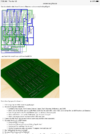
I sent PCBPrime 8 files: Hole report, drill file, layer 1, layer 2, solder mask 1, solder mask 2, silkscreen, and a PDF document, showing all the files in postscript form, generated by the program. So, I don’t know what I’m missing, except for the board outline, and I specifically asked for help with how I might indicate that. And didn’t get answer. (Does it seem like they’re blowing me off... “missing many files...ETC.”?) That was one of the reasons I abandoned PDF2Gerb. I didn’t understand what that site (https://swannman.github.io/pdf2gerb/) had to say about the board outline.
OsmondPCB says nothing about board outline. Although, I think I read somewhere in the documentation that they assume a rectangular board. I just figured that the “work space” that you set up translates as the board outline. But, I’ve asked PCBPrime if I should manually draw it on one or more layers.
I’m working on an old iMac and was thrilled that OsmondPCB offered a version of their software that would work on it. I thought I had it pretty much figured out... I’ve emailed Swannman and [email protected] with questions and have received no replies.
I’ve got all the files on my mediafire page. I can get that link, if anyone has the time to look through them. Or I can upload the PDF file here.
THANKS for any and all help!
——-
Here is your quote that I could do with what you sent me. There seem to be quite a few files missing (i.e. Board Outline, Soldermask files, etc.)
Do you have the ability to export the files into 274X format?
——-
Meanwhile, here is what the Osmondpcb.com site claims about their software:
“Once your design is complete, Osmond can produce standard Gerber (RS-274X) files and Excellon drill files that fabricators use to make your boards.”
——
I sent PCBPrime 8 files: Hole report, drill file, layer 1, layer 2, solder mask 1, solder mask 2, silkscreen, and a PDF document, showing all the files in postscript form, generated by the program. So, I don’t know what I’m missing, except for the board outline, and I specifically asked for help with how I might indicate that. And didn’t get answer. (Does it seem like they’re blowing me off... “missing many files...ETC.”?) That was one of the reasons I abandoned PDF2Gerb. I didn’t understand what that site (https://swannman.github.io/pdf2gerb/) had to say about the board outline.
OsmondPCB says nothing about board outline. Although, I think I read somewhere in the documentation that they assume a rectangular board. I just figured that the “work space” that you set up translates as the board outline. But, I’ve asked PCBPrime if I should manually draw it on one or more layers.
I’m working on an old iMac and was thrilled that OsmondPCB offered a version of their software that would work on it. I thought I had it pretty much figured out... I’ve emailed Swannman and [email protected] with questions and have received no replies.
I’ve got all the files on my mediafire page. I can get that link, if anyone has the time to look through them. Or I can upload the PDF file here.
THANKS for any and all help!


