Maker Pro
Maker Pro

Fix needed for LED indicator in switching circuit. Everything is lighting up.

ALB10811

Oct 27, 2023
4
Joined
Oct 27, 2023
Messages
4
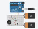
Hi I'm trying to design a circuit that switches between a manual button push to activate a relay and an Arduino output to activate the relay. I can get the switching and relay working fine however I want to add two LEDs to indicate which output is currently selected. I need an LED to light up constantly if the switch is on the Arduino but not to trigger the relay unless there's an output from the Arduino. The circuit below just lights everything up regardless of which side the switch is on when there is an output from the Arduino. Is there any way to fix this?

1698371465665.png
 

ALB10811

Oct 27, 2023
4
Joined
Oct 27, 2023
Messages
4
This might be a better schematic. I have put a piezo inplace of the relay.
1698377665195.png
1698377751553.png
 

Harald Kapp

Moderator
Moderator
Nov 17, 2011
13,769
Joined
Nov 17, 2011
Messages
13,769
Your description of the intended function is unclear:
Do you want the relay to be activated either by the switch or by the Arduino?
Or do you want a selector switch that allows you to chose whether the relay shall be activated by the Arduino or a pushbutton?

Regardless of which of these: Your circuit will not work.
  • why would you use 2 batteries?
  • when using multiple batteries they need a common connection. Usually GND (Bat-) is used for that.
  • an Arduino output can't drive a relay directly. You will need an additional driver. A simple NPN transistor or N-Mosfet will do.
  • in your 2nd schematic, output U1_D13 is short circuited to BAT2- via D1 and D4.
  • plus maybe other irregularities. I didn't care to check for more detail after noting the above.
This is the most simple circuit I can envision that allows a relay (represented by L1) to be activated either by a logic signal (from_Arduino) or a switch:
1698383563333.png
Note the freewheeling diode D1 which is required to protect the transistor Q1 from voltage spikes when turning the relay off.
 

ALB10811

Oct 27, 2023
4
Joined
Oct 27, 2023
Messages
4
Hi, thank you so much for your reply. I don't need the Arduino to drive the relay it's on a relay board designed for Arduino so it just needs the 5v output to work the relay. The basic circuit I have works. I have a SPDT switch with ON-ON-OFF positions. The 1st ON position is for the user to give the relay a manual hit to turn on the relay. The 2nd position lets the programmed Arduino run a set series of outputs to turn the relay on and off as per the program. The 3rd position is OFF so no input from either manual or Arduino. I have an LED that works fine lighting up when there is either a manual hit or an output from the Arduino. The issue is I don't know what position the switch is in when on Arduino or off so I'm trying to put in a 2nd LED which is constantly on when the switch is in the 2nd Ardunio position but I don't want the relay to be on as I need the Arduino to be able to run it's on off program. I added the 2nd battery and created the short trying to introduce the 2nd LED. I thought if I put it on a separate circuit with just a ground for the continuity of the switch it would work but it doesn't. I was hoping for some help on a way to do this.
 
Last edited:

Harald Kapp

Moderator
Moderator
Nov 17, 2011
13,769
Joined
Nov 17, 2011
Messages
13,769
Use a double pole 3-position switch.
Use 1 pole to select between "manual", "Arduino" and "off".
Use the 2nd pole to activate the indicator LEDs. No 2nd battery needed.
 
Top