Maker Pro
Maker Pro

How to safely short the leads of a DC motor together with no power is applied.

RichC

Dec 5, 2023
6
Joined
Dec 5, 2023
Messages
6
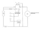
I have made a crab pot puller using a wheelchair 12Vdc 4 brushes 1000W motor. My control circuit is attached. The problem is when the power is turned off the motor unwinds under the weight load . I know that by shorting the leads will give me some braking. I am looking for a relay that will replace the present one I am using that is a 100A continuous duty solenoid. The quest is how to I add another relay that will safely handle the load protect things from causing accidental damage? I have been searching for a SPDT solenoid coil to replace the one I am using but Ihavenot found one that shows a diagram of how they work. I am hoping someone here can help me past my road block
 

Attachments

  • Crab Davit Circuit.pdf
    53.7 KB · Views: 2
  • Controlbox.jpg
    Controlbox.jpg
    457.5 KB · Views: 4

danadak

Feb 19, 2021
797
Joined
Feb 19, 2021
Messages
797
Automotive starter relays and solenoids pretty cheap. But they are SPST, typically.

1701798616925.png


Regards, Dana.
 

Minder

Apr 24, 2015
3,479
Joined
Apr 24, 2015
Messages
3,479
Replace the existing relay with a DPDT, the other set of contacts will provide the short across the motor. when it is de-energized.
 

RichC

Dec 5, 2023
6
Joined
Dec 5, 2023
Messages
6
Automotive starter relays and solenoids pretty cheap. But they are SPST, typically.

View attachment 61956


Regards, Dana.
Thankks Dana,
I already using a starter solenoid that is SPST and I need one that is SPDT but I have not located one that shows a schematic of how it works.
Rich
 

Bluejets

Oct 5, 2014
7,057
Joined
Oct 5, 2014
Messages
7,057
Would work much more reliably using a mechanical one way clutch.
Dynamic brake requires motor to be spinning and is commonly applied during rundown time, not as a brake to stop the motor turning in reverse.
 

RichC

Dec 5, 2023
6
Joined
Dec 5, 2023
Messages
6
Thank you for the input. If this was a worm gear drive the present setup would work fine. I have test the shorted leads and results are such that the 50 pound weight is slowed way down to make a more manageable situation to safely put the rope in a cleat.
 

Bluejets

Oct 5, 2014
7,057
Joined
Oct 5, 2014
Messages
7,057
If this was a worm gear drive the present setup would work fine.
Only if the worm angle is above a certain angle......anything below this "critical angle" and it WILL drive backwards.

As for a shorting relay, could use a starter solenoid which has 2 connections to the coil.
 

Attachments

  • Image1.jpg
    Image1.jpg
    12.1 KB · Views: 0

crutschow

May 7, 2021
861
Joined
May 7, 2021
Messages
861
I need one that is SPDT but I have not located one that shows a schematic of how it works.
The COM terminal goes to the motor, the N.O. terminal goes to the power supply, and the N.C. terminal goes to ground/common.
The motor then receives the supply voltage when the relay coil as powered, and is grounded when the relay coil is not powered.

1701877976747.png
 

RichC

Dec 5, 2023
6
Joined
Dec 5, 2023
Messages
6
Thanks all for the responses. I think I have the proper solenoid that will fit in the space and do what I need. I purchased a COLE HERSEE 24401 12V insulated which is 6poles.These are used in golf carts and winches. Once I receive it and hook it up I will report back the results.
 

crutschow

May 7, 2021
861
Joined
May 7, 2021
Messages
861
I purchased a COLE HERSEE 24401 12V insulated which is 6poles.
That's an 85A rated unit. I thought you wanted 100A?

As Minder's schematic shows, it is a DPST (alternate poles on).
It has 6 terminals but not 6 poles (as defined by relay convention "The pole of a relay is the terminal common to every path. Each position where the pole can connect is called a throw.").
To use it for your purpose you can connect terminals 1 and 5 to the motor, terminal 4 to power, and terminal 6 to ground.
 
Last edited:

RichC

Dec 5, 2023
6
Joined
Dec 5, 2023
Messages
6
Thank Minder for the schematic as this will be helpful.

Also thanks crutschow for the explanation on poles verse terminals. Never to old to learn! The 85A will be fine. The motor is a 1000W and at 12V that is 83.3A on the initial surge I will use your connections to put in my circuit that I attached in my initial post. I will update the results once I have thing in place.
 

crutschow

May 7, 2021
861
Joined
May 7, 2021
Messages
861
The motor is a 1000W and at 12V that is 83.3A on the initial surge
The starting current for a motor can be several times its rated power (mainly determined by its winding resistance), but that relay will probably handle it.
You can measure the motor resistance with an ohmmeter to get an idea of the actual starting current.
(Be sure to subtract the ohmmeter reading
with the leads shorted, from the motor reading to get a more accurate value).
 
Last edited:

RichC

Dec 5, 2023
6
Joined
Dec 5, 2023
Messages
6
Hello and Merry Christmas and a Happy Healthy New year to all,

Here is the follow up to close out this thread on my braking questions for the DC motor. I have installed the the new 6Terminal solenoid wired it up per Minder's suggestion. I am happy to report all is working well and the braking is doing as I had hoped. I have attached my version of the whole circuit. The air momentary switch is operated by a phonematic footswitch .

I want to thank everyone who responded and guided me through this.
RichC
 

Attachments

  • Motor Circuit.jpg
    Motor Circuit.jpg
    87 KB · Views: 3
Top