Maker Pro
Maker Pro

I want to know all of the maths concerning this scissor mechanism!

Bluejets

Oct 5, 2014
7,048
Joined
Oct 5, 2014
Messages
7,048
Looks like something Gyro Gearloose might help you with......... either him or GoGo Gadget.
 

Maglatron

Jul 12, 2023
1,640
Joined
Jul 12, 2023
Messages
1,640
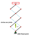
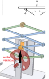
I want to use the scissor mechanism in conjunction with the mechanism (that I posted in another thread) to lift the weight of 275grams a hieght of 1.26m and drive the cam with the motion of the wheel!View attachment 63745View attachment 63746my thinking is that if the wieght is lifted quickly it won't have the time to slow the wheel (too much) it's impulse; whereby if a thing is moving, then it provides a really high force at impact to slow it down, the faster it's slowed the higher the force on impact, so taking advantage of the high force as a product of the change velocity and inertia and the time it took, thanks in other words, it takes a really high force to change the momentum quickly especially if the unit of momentum is high and me thinks this high force short time will be enough to lift the wieght up if the scissor and cam are designed correctly, not looking for you to work it our for me I just want the equations and formulas to work it out myself I've just bought 3 books on the matter of mechanisms and the math to go along with it so might not need the help if the stuff I need is in the books!!
you can ignore the problem in the image! that was something else! thanks
 

Maglatron

Jul 12, 2023
1,640
Joined
Jul 12, 2023
Messages
1,640
I'm fmiliar with the scissor lift and mechanism Dave, but curious as to the TS's intended use of it.
so I know you said your maths is a bit rusty but could you shed any light on the mechanism, maths wise? thanks
 

Alec_t

Jul 7, 2015
3,644
Joined
Jul 7, 2015
Messages
3,644
I think if you swot up on the lever principle and the moment of inertia of a rotating body, plus Newton's Laws, you will have all you need to do your calculations.
 

Maglatron

Jul 12, 2023
1,640
Joined
Jul 12, 2023
Messages
1,640
ok here's another for your viewing pleasure this is not got the scissors in though
 

Attachments

  • snail shell.png
    snail shell.png
    45.3 KB · Views: 4

Maglatron

Jul 12, 2023
1,640
Joined
Jul 12, 2023
Messages
1,640
how would you go about modelling the scissor mechanism with the lever principal, this might take me a while so please bare with!
 

Delta Prime

Jul 29, 2020
2,115
Joined
Jul 29, 2020
Messages
2,115
I don't get it!
I believe you insulted me
Believe it or not I never said that I never posted that I never wrote that down speech to text or anything!!!!
Anyway....
If the content peaks your interest take a look at the PDF.
"People who make the rules also make exceptions for themselves."
-Delta Prime
photo_1716566146003.png
 

Attachments

  • ADA225220.pdf
    1.6 MB · Views: 2

Maglatron

Jul 12, 2023
1,640
Joined
Jul 12, 2023
Messages
1,640
can you point me to a competent web page to learn about levers, youtube isn't that great! also for Mr Delta Prime no where in that document does it mention the design I want as I said I need to have one like this
 

Attachments

  • scissor yes.png
    scissor yes.png
    20.6 KB · Views: 0
  • scissor no.png
    scissor no.png
    102.7 KB · Views: 0
Last edited:

Delta Prime

Jul 29, 2020
2,115
Joined
Jul 29, 2020
Messages
2,115
6
Mr Delta Prime no where in that document does it mention the design I want as I said I need to have one like this
My good man I have given you the foundation to which to build upon. It is straightforward!
Nevertheless I will try to break it down for you even more. I'm on break I'll see you at lunch.

photo_1716570475351.png
 

Maglatron

Jul 12, 2023
1,640
Joined
Jul 12, 2023
Messages
1,640
sorry man its a lot of working out I'm not interested in the forces in the z or x axis or if it topples, I am not designing a scissor lift I just want to know, 1) ratios between the input distance moved and output distance moved, 2) the mechanical advantage of the of this very simpe machine, 3)and how adding a stages changes the outcome (distance moved and loss in force) I think it has a negative mechanical advantage because mechanical advantage there is a trade off between force and distance, unless you want to give it a crack and explain to me these three things, thanks everyone looking for a simple option to work out the things mentioned, thanks
 
Last edited:

Alec_t

Jul 7, 2015
3,644
Joined
Jul 7, 2015
Messages
3,644
For the arrangement in post #34 your input force is applied to the pivot at level 4. If that pivot moves a distance dy vertically, then the corresponding pivots at level 3, 2, and 1 will move vertically by 2*dy, 3*dy and 4*dy respectively. The load platform is a half-level above level 1, so the total distance it moves will be 4.5*dy.
If the platform is stationary and there are no horizontal forces acting on the mechanism, then the vertical upward force at each of those pivots must equal the weight of the (loaded) platform. So, applying just the input force as shown offers no mechanical advantage.
 
Last edited:

Maglatron

Jul 12, 2023
1,640
Joined
Jul 12, 2023
Messages
1,640
thank you Mr Alec_t thats really helpfull let me just redraw for clarification of where the load would be, so by what you were saying then the force applied to the pivot at level 4 moves a distance dy then the load would move in the y direction 4*dy and that is the ratio of the displacement and by the mechanical advantage if I put a unit of force into the level 4 then the it would get divided by 4 too
so I think you are correct to a certain degree, but in my head if the length of the crossing bits of metal on the scissor (for want of a better description, I don't know their name) I think the length of these would have an impact on the hieght that the top level would go, tell me if you think I'm wrong, cheers watch this again
1716575936169.png
 
Last edited:

Maglatron

Jul 12, 2023
1,640
Joined
Jul 12, 2023
Messages
1,640
so relating this back to my mechanism I need to
to lift the weight of 275grams a hieght of 1.26m
In 1 second how much force would one need
For the arrangement in post #34 your input force is applied to the pivot at level 4. If that pivot moves a distance dy vertically, then the corresponding pivots at level 3, 2, and 1 will move vertically by 2*dy, 3*dy and 4*dy respectively. The load platform is a half-level above level 1, so the total distance it moves will be 4.5*dy.
If the platform is stationary and there are no horizontal forces acting on the mechanism, then the vertical upward force at each of those pivots must equal the weight of the (loaded) platform. So, applying just the input force as shown offers no mechanical advantage.
and the platform is free to move up and down if you take a look the support on the right side of the platform is a roller!
 
Last edited:

Maglatron

Jul 12, 2023
1,640
Joined
Jul 12, 2023
Messages
1,640
lets just work out what force is needed to lift the weight of 275grams a hieght of 1.26m in 1 second, thanks if the snail shell cam max radius is 0.12m and the radius of the thinest part of the cams radius is 0.05m spiraling outward, force needed equals 0.2753233775 * 9.80665 = 2.7N hmmm
 
Last edited:

Maglatron

Jul 12, 2023
1,640
Joined
Jul 12, 2023
Messages
1,640
F = m g
gravitaional force, weight mass m (0.2753233775 kg)
g acceleration due to gravity 9.80665m/sec^2

Fgrav = 2.7N

force for upward acceleration F = m a
m = (0.2753233775 kg)
a = 1m/sec^2 (arbitrary acceleration)

Facc = is just 0.2753233775N

total force required

Ftot = Fgrav+Facc
2.975323377N

or 2.98N rounded off
 
Last edited:
Top