Maker Pro
Maker Pro

Is that a fuse or resistor

pharaon

Oct 28, 2014
444
Joined
Oct 28, 2014
Messages
444
Is that blown item is fuse or resistor, and is it possible to replace those SMD didoes with usual one?must the four bride SMD didoes be replaced or can i replace only two that is faulty with regular 1n4007


Last edited:

Bluejets

Oct 5, 2014
6,942
Joined
Oct 5, 2014
Messages
6,942
fuse or resistor

Probably both, a fusible resistor.

Not common to replace just individual diodes in a bridge.
Space might be a problem replacing with axial type diodes.

I'd say some other fault there as well, not just the ones you point to.
 

pharaon

Oct 28, 2014
444
Joined
Oct 28, 2014
Messages
444
I'd say some other fault there as well, not just the ones you point to
That fusible resistor and two smd diodes,
What item should I use for that fusible resistor cause I can't find the same should I use fuse or resistor
 

73's de Edd

Aug 21, 2015
3,629
Joined
Aug 21, 2015
Messages
3,629
Sir pharaon . . . . .

Correct, in that units 
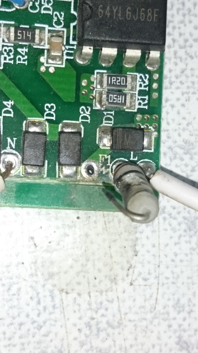
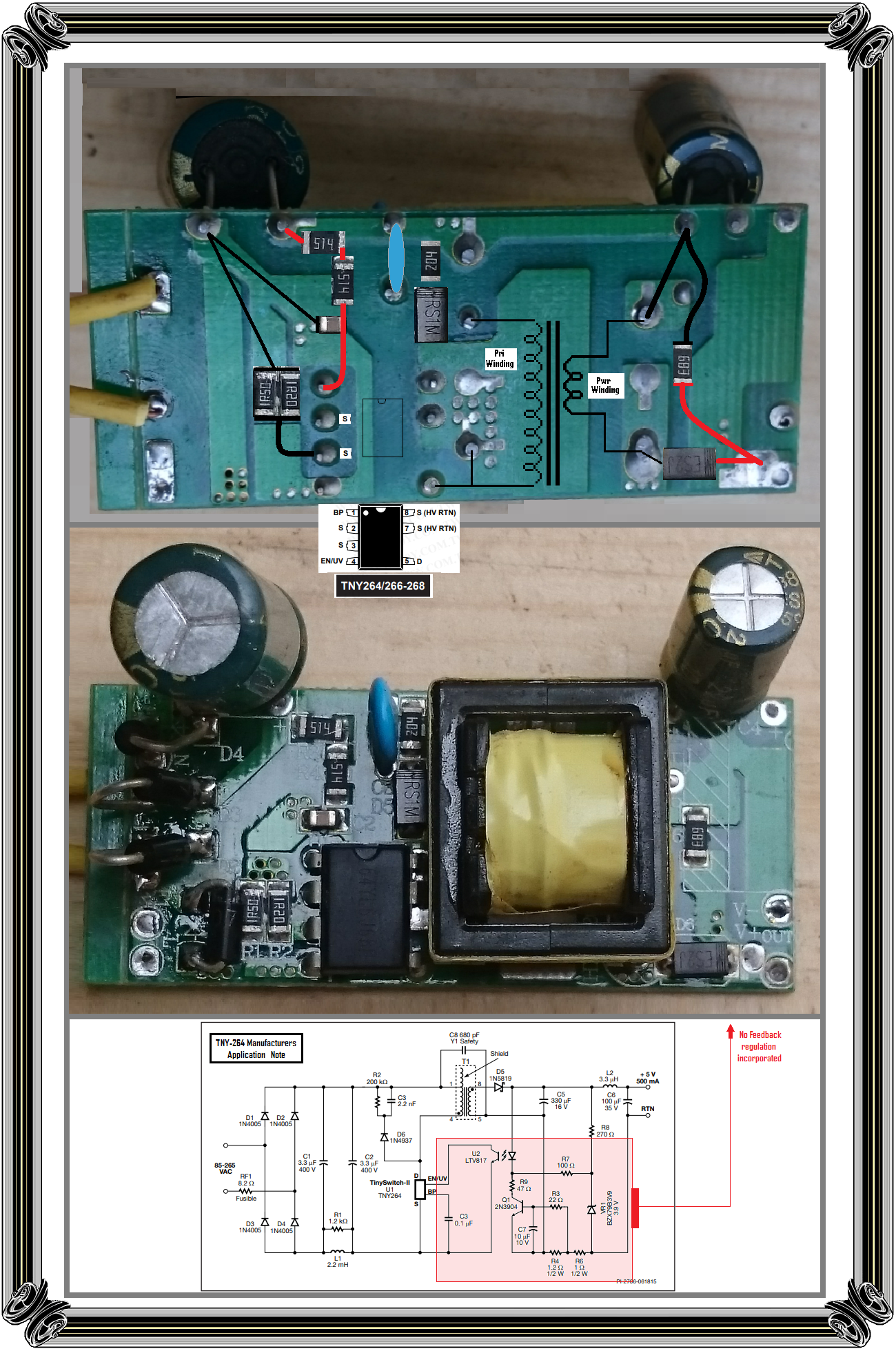
Surface Mount . . . M7's . . .equate in electrical equivalency to a leaded general purpose 1N4007 diode .
You could ease the sharpness of bend at the case and form into this *** shape, to get two folded under tabs to solder to the foil lands. You PRE TIN both the lead tabs and the foil lands by adding fresh solder to the foil tabs and then micro position and reflow solder them .

***
upload_2020-6-20_22-11-28.png

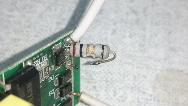
OR . . . . you could fold a diodes end lead over and mount them vertically, such as the F1 resistor is now done.

Just don't get so DEEPLY engrossed in the mounting aspects, such that you acidentally get 1 or more diodes polarity-(ies) installed backwards . . . . . . the power supply . . . . . it then go BOOM ! ! ! . . . . on power up.

Replace all 4 of the original units in order to maintain a "balanced" set of 4 new diode junctions.
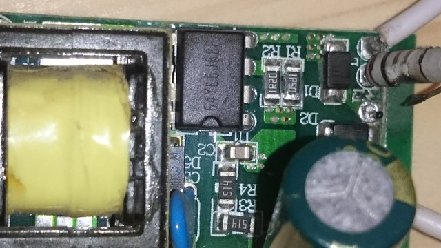
Your pic didn't quite all encompass, in showing the 
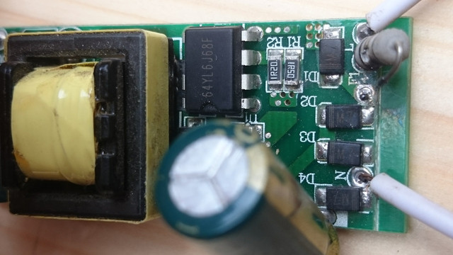
MAGIC part number on the 8 pin IC nearby.
It is probably enclosing a now dead shorted POWER FET built within it . . . . or else . . .that chip feeds over to driving a separate . . . . shorted out ? . . . .POWER FET.
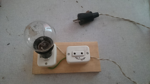
I wouldn't worry about that popped 10 ohm resistor for just now, and just wire in leads to a 60 watt incandescent lamp, until testing with it during power up, then reveals, no further defective component problems .

Then, the use of a 10 ohm carbon film type would blow open at the lowest overload level of loading . . .fast acting . . ., whereas a metal film unit would give more time lag . . . .it appears that original unit is being metal film unit.

Thaaaaaaaaaassssit . . . . .

73's de Edd . . . . .


I'm not a snob. . . . . . . I'm just better than you are.


.
 

Bluejets

Oct 5, 2014
6,942
Joined
Oct 5, 2014
Messages
6,942
Seems an odd-ball ic...nothing came up on a quick search....
Test for any shorted pins...sometimes they use multiple pins for the mosfet so that might be an indicator...
 

73's de Edd

Aug 21, 2015
3,629
Joined
Aug 21, 2015
Messages
3,629
Sir pharaon . . . . .

Gimme a good closeup of the other side of the . . .double foil sided . . . board so dat I can reads it . . . . .as it is now, a highly educated guess would be that it is a TNY 264.
Thaaaaaaaassssssit . . . .

73's de Edd . . . . .
 
Last edited:

pharaon

Oct 28, 2014
444
Joined
Oct 28, 2014
Messages
444
Ok changed the diodes, I'm hearing like buzz from the circuit but no output Dc while connecting to 60 wat lamp in series
It's a led light Power supply by the way
 

73's de Edd

Aug 21, 2015
3,629
Joined
Aug 21, 2015
Messages
3,629
Sir pharaon . . . . .

I'm hearing like buzz from the circuit but no output Dc

Any chance that the secondary rectifier might be bad ?

A double sided board in two shades of green mask with that style of vias is not too easy to read , but I made out the rank principals.
WITH an additional major hindrance of not having board in hand to take ohms readings.
The mentioned IC seems to fit to the board traces. I submitted a typical use/ application as the very bottom reference..
There are aditionally the two SM low value . . .0.6 ohm . . . resistors being in a series loop within the power circuitry.
There is the same R/C snubber and companion series damping diode, associated witth the primary of the transformer winding.
There are the series pair of 510k " bump up " resistors to initially start up an AC powered down unit.
The secondary has just a Schottky diode and its power reservoir filter E-cap and a 68K bleeder resistor.
What are the two E-caps . . .on the primary and secondary . . . .their voltage and capacitance values ?.
Particularly the secondary LED supply voltage as it might be supplying for either a 30-60 or 90 volt series configured LED string .
( But you have said no DC there. )
A nearby lightning bolt to the power line was the probable cause of the units outage.
If you are uncertain of the lamps LED strings condition . . .of having a possible open LED in the string . . . I would be using yet another incandescent lamp in their place. Then you would have some degree of glowing light level if they were receiving DC power from that secondary.
Now . . . the already installed test lamp in place of the fuse might be cramping the supplies power output level. So if the F1 . . .test lamp is not BRIGHT . . . . AND your primary E-cap has lived thru having had RAW AC to it until F1 blew open .
And you have placed an AM radio, tuned off from any stations on top of the Sw Mode power transformer and it is going crazy with radiated RF sub harmonics . . . . indicating a definite power swithching ction , occurring in the primary transformer circuit.
Do a spot check of the DC output voltage at your V+ and V - terminals with a loading.
If all seems to be somewhat normal you might chance a 1-2 second shorting across the test lamp to see if full power is permissible, and will run allright that way.
If so, then temporariy use a 10 ohm carbon film for R1, for further protected voltage analysis.

The floor is now open for further questions.

BOARD REFERENCES . . . . .
SMPS-LED-Supply.png


https://i.ibb.co/YXG3h9d/SMPS-LED-Supply.png

FULL TNY 264 Data Sheet . . . . .

https://datasheetspdf.com/pdf-file/798288/PowerIntegrations/TNY264/1


73's de Edd . . . . .


Must have info . . . . A Cycles to Hertz Cross Conversion Chart:

https://www.kb6nu.com/wp-content/uploads/2012/04/cps-hertz-chart.png

.
 

pharaon

Oct 28, 2014
444
Joined
Oct 28, 2014
Messages
444
Any chance that the secondary rectifier might be bad ?
No it's alright

What are the two E-caps . . .on the primary and secondary . . . .their voltage and capacitance values ?.
400V 15μf
100V 22μf

Particularly the secondary LED supply voltage as it might be supplying for either a 30-60 or 90 volt series configured LED string .
( But you have said no DC there. )
It's for 60V led light, I've tested with DMM and didn't get dc read

If you are uncertain of the lamps LED strings condition .
I bought new LED string, but waiting to fix the power supply before I connect it

Now . . . the already installed test lamp in place of the fuse might be cramping the supplies power output level. So if the F1 . . .test lamp is not BRIGHT . . . . AND your primary E-cap has lived thru having had RAW AC to it until F1 blew open .
I didn't put the lamp on the fuse place, I have it as AC in to the circuit so if there any short in the circuit it will light


And you have placed an AM radio, tuned off from any stations on top of the Sw Mode power transformer and it is going crazy with radiated RF sub harmonics . . . . indicating a definite power swithching ction , occurring in the primary transformer circuit.
Yes, and also i could hear the buzz without the AM radio although it was very low

Do a spot check of the DC output voltage at your V+ and V - terminals with a loading
Will try, but what kind of load?
 

WHONOES

May 20, 2017
1,217
Joined
May 20, 2017
Messages
1,217
You most likely need a load on the output for the switching circuit to work at all. Most of these types require a minimum load probably around 5% of rated output. Though having said all that I would expect to see some sort of voltage on the output, it would likely be very low though. According to the datasheet, the switching frequency is jittered at 1Khz which may account for what you are hearing.
Further, The TNY263 has a Line under voltage detector that switches off the switching FET until the condition is corrected therefore, the lamp in place of the resistor on the input may be causing that problem.
I suggest that you have a read of the datasheet (see below) which may help.

https://www.power.com/sites/default/files/product-docs/tny263_268.pdf
 

73's de Edd

Aug 21, 2015
3,629
Joined
Aug 21, 2015
Messages
3,629
Sir pharaon . . . . . .


O.K.
you are being fine on having the lamp in series with the AC power into the unit . . . .that then will provide "blow up " protection to your unit at power up for initially testing the ¿ repaired ? unit.

BUT . . . with your last photo you still have an open AC input circuit to the FWB rectifier configuration, just by virtue of there being no closed power input circut, via the missing F1 fuse resistor.

SO just get installed, EITHER a carbon film or a metal film resistor of 10 ohms value . . . . .guesstimate the wattage by using the same size as the pulled unit . . . . . we'll then worry about the specific, proper, gold plated, diamond encrusted version LATER.

As for the AM radio,I think that you were merely hearing expected AC line noise.
With that IC circuit powered up and working properly, its strong radiated harmonics, that extend well on up into the Low RF spectrum, will DEFINITELY let you know that you truly have some SWITCH MODE power switching action going on.

You can even further confirm this . . . . in showing your self WHAT sound your ears are expected to be hearing . . . . by using either a wall wart that is of SMPS design inside OR even some of our CFL or LED light bulbs and "kissing" them with your small radio. ( The SMALL radio aspect, is being in order to get right on in and being capable of being placed physically CLOSE to them. )
Then, after hearing that aural effect, remove the power to the device and listen to the main filter capacitor drain down and cause a simultaneous SHIFT of the received tone downwards until it finally drops off. . . . . . and then there will be just the residual AC power line noise that you WERE hearing.

73's de Edd . . . . .


Any sufficiently highly advanced modern technology is hardly indistinguishable from magic.

.
 
Last edited:

pharaon

Oct 28, 2014
444
Joined
Oct 28, 2014
Messages
444
BUT . . . with your last photo you still have an open AC input circuit to the FWB rectifier configuration, just by virtue of there being no closed power input circut, via the missing F1 fuse resistor.
i already connect the input after the fuse since i don't have the fuse installed on

As for the AM radio,I think that you were merely hearing expected AC line noise.
With that IC circuit powered up and working properly, its strong radiated harmonics, that extend well on up into the Low RF spectrum, will DEFINITELY let you know that you truly have some SWITCH MODE power switching action going on.
the noise were from the IC circuit not the AC line noise.that's why it keep getting slow on the radio till it fade out when i disconnect the AC power
 

pharaon

Oct 28, 2014
444
Joined
Oct 28, 2014
Messages
444
You most likely need a load on the output for the switching circuit to work at all. Most of these types require a minimum load probably around 5% of rated output.
ok i tested with the LED strip and it work fine, you were right it needed a load to work
 

Bluejets

Oct 5, 2014
6,942
Joined
Oct 5, 2014
Messages
6,942
The fusible resistor serves a dual purpose in that it reduces inrush at startup.......so both really.
You do realise they are available in places like Ebay etc. ...?
 

bertus

Moderator
Nov 8, 2019
3,336
Joined
Nov 8, 2019
Messages
3,336
Hello,

This video will explain the fusible resistor:


Bertus
 
Top