Farukh Khan
- Jun 12, 2015
- 160
- Joined
- Jun 12, 2015
- Messages
- 160
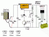
Hello Guys,
I got a 12V 7.2AH Gel Cell Battery. I want to make a charger circuit for my battery. I got a 24V 20A Power Supply for my whole system. So here I got a circuit diagram. But I am not sure if the circuit will charge my battery fast and safely using the power supply I have. I am attaching the circuit diagram in this post. If there is any fault in the diagram then share it with me. Please suggest me any changes that I need to make the circuit a safe and fast charger using my 24V power supply. As I think the circuit is for max 18V supply. So please suggest me how will I adapt it for my 24V supply.'
Thanks in advance......