Maker Pro
Maker Pro

Just need a "simple" question answered around something I'm designing it's mechanical in nature but confident there are people who may be able to help

Maglatron

Jul 12, 2023
1,644
Joined
Jul 12, 2023
Messages
1,644
The accuracy for me is essential because if I round up or down there are always massive discrepencies in the later calculations, so I use all the digits it displays on my calculator and although it's probably not completly required it does feel good when the numbers line up exactly and to the point. I do realise that this machine could not be made practically speaking but my question is how do change the gear so I use the same weight to fall in 15 seconds, keeping the angular acceleration of 0.05rad/sec^2. If you could entertain the idea for sake of understanding I would be highly greatfull!! thanks Mr Alec_t
 
Last edited:

Maglatron

Jul 12, 2023
1,644
Joined
Jul 12, 2023
Messages
1,644
what do you mean I posted the pic here! here it is again
Could you provide a link to the photo you posted about (project jpeg).
I'm having difficulty following your simple question thank you.
 

Attachments

  • project.jpg
    project.jpg
    115.8 KB · Views: 1

Delta Prime

Jul 29, 2020
2,137
Joined
Jul 29, 2020
Messages
2,137
what do you mean I posted the pic here! here it is again
I need the source of that pic.
I do realise that this machine could not be made practically speaking but my question is how do change the gear so I use the same weight to fall in 15 seconds, keeping the angular acceleration of 0.05rad/sec^2.
this one paragraph makes sense.
My goal is to condense all the information you provided into something coherent.
And then ask the question for you on the website physics.com.
 

Maglatron

Jul 12, 2023
1,644
Joined
Jul 12, 2023
Messages
1,644
I drew it in paint and it is coherent! I explained it with steps and I wrote out the proccess twice! and I think that if you can't understand what I said then when they ask you a question you might not have the insight to reply and thats only because I thought of it nothing else
I need the source of that pic.

this one paragraph makes sense.
My goal is to condense all the information you provided into something coherent.
And then ask the question for you on the website physics.com.
 

Maglatron

Jul 12, 2023
1,644
Joined
Jul 12, 2023
Messages
1,644
so here is the diagram all labled upproject labled.jpg
 
Last edited:

Maglatron

Jul 12, 2023
1,644
Joined
Jul 12, 2023
Messages
1,644
I need the source of that pic.

this one paragraph makes sense.
My goal is to condense all the information you provided into something coherent.
And then ask the question for you on the website physics.com.
did you end up making sense of the diagram and description Mr Delta Prime???
 

Maglatron

Jul 12, 2023
1,644
Joined
Jul 12, 2023
Messages
1,644
I've edited the description of the workings of the device so hopefully easier to read and understand

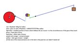
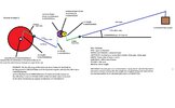
I want my flywheel whose inertia is 10.8kgm^2 and initial velocity is 3.3873422rad/sec, (after the 18th drop) it has a gear on the axle of it whose radius is 0.0002777777778m. And a lever, whose load side is 0.005m and effort side 0.3m (this is to the right of the wheel) and the arc length on the load side is 0.001745329252m, and because it moves through the angle, and 0.3490658504rad * the length of the load side lever (0.005 ) and 0.001745329252m is also the circumference of the gear on the axle of the flywheel and that's radius is 0.0002777777778m! the effort side moves up which in turn moves the wheel clockwise. an arbitrary angular acceleration is chosen as to be 0.05rad/sec^2. torque equation states that the inertia * angular acceleration equals torque 10.8 * 0.05 = 0.54Nm. torque/radius of gear equals is tangential force 0.54/0.0002777777778m = 1944N. then 1944 * length of load side of the lever = torque, so 1944 * 0.005 = 9.72Nm. then to find the force needed on the end of the lever (over to the right more) 9.72/0.3 = 32.4N moving upwards, find length of arc on effort side of lever one, s = r theta 0.3 * 0.3490658504 = 0.1047197551m, then we make that distance the circumference of the driver gear on a compound gear the bigger one is the driver and the smaller one is the driven so 0.1047197551m/2pi equals the radius of the larger gear on the compound which is 0.01666666667m. make the driven gear 5 times smaller and multiply the force by 5, so 32.4 * 5 = 162N and the radius of the smaller gear is 0.01666666667/5 = 0.003333333334m, then for continuity multiply 162 * 0.003333333334 = 0.54Nm. add an idler gear between the smaller gear on the compound and the toothed portion of the arc of the load side on lever two to make the flywheel turn clockwise. The size of the idler gear is unimportant because it's an idler gear. Make the circumference of the driven gear the distance the load side arc length 0.003333333334 * 2pi = 0.02094395103m. s = r theta, s / theta = r , 0.02094395103/0.3490658504 = 0.06m. 0.06 is the length of the load side of the 2nd lever multiply by 60 because that was the ratio of the first lever and that equals 3.6m for the 2nd lever effort side. Next find the distance of that the end of the effort side is lifted! s = r theta, 3.6 * 0.340658504 = 1.256637061m. then divide 162/60 = 2.7N so the weight of the block that pulls down on the end of the second lever 2.7/9.80665 = 0.2753233775kg then we have torque match up with 2.7N * 3.6m = 9.72Nm, then for energy; F * d 2.7 * 1.256637061 = 3.392920065Joules torque time theta 9.72 * 0.3490658504 = 3.392920066J mgh 0.2753233775 * 9.80665 * 1.256637061 = 3.392920065J to work out the equation for E = 1/2 I * w^2 we must find the angular velocity w2^2 = w1^2 + 2 alpha * theta (w1 is 3.293291461 (after the 18th drop) ) = 3.293291461^2 + 2 * 0.05 * 2pi rad = 11.47408718 take the root and it gives 3.3873422rad/s so plug into energy equation E = 1/2 * 10.8 * 3.3873422^2 which equals 61.96007077J analyse and summarize

I want to edit the gearing so that it takes 15 seconds for the weight to drop on the 19th time round whilst maintaining angular acceleration of 0.05rad/sec^2
and I would like a equation to calculate the linear velocity of the block right before the block hits the floor aswell

I've just realised that all the time I said to the left I meant to the right sorry to confuse!!! now it corrosponds to the diagram again apologies thinking of doubling the larger gear on the compound to 10:1 rather than 5:1 and see what changes (angular acceleration of the flywheel wise)
 

Attachments

  • project labled.jpg
    project labled.jpg
    155.4 KB · Views: 1
Last edited:

Maglatron

Jul 12, 2023
1,644
Joined
Jul 12, 2023
Messages
1,644
UPDATE: I'm chaging the bigger gear on the compound to twice the size (10:1 instead of 5:1) and working out the angular acceleration difference of the flywheel, procrastinating though must do it soon! thanks
 

Maglatron

Jul 12, 2023
1,644
Joined
Jul 12, 2023
Messages
1,644
so I did what I said I was going to and made the larger driving gear on the compound 2ce the size and effectivly made it 10:1 ratio, this time the energy is passed over to the wheel but it take Exactly 2ce as long to do it so whats goin on here with this - energy and power wise? bassically the power is halved for the slower one! thats where i'm at, think in terms of power and not just energy like this 1watt in half watt out!
 
Last edited:
Top