HEY! . . .HEY . . .HEY! . . . . .Sir Zee Jay Ess !
Let's see if I can totally fill you in to . . . . . getting beyond your current impasse . . . . . whereupon your extended length of cable at the lop left corner, on past the
J marker . . . . . . can finally get its proper routing.
It seems like your received references from the peanut gallery, are being
WAAAAAAY older than your unit actually is.
I look at just one component part on your photo content and relate to its telling me that unit is being mid
1975 vintage.
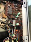
The motor presence in left foreground
ALSO tells me that the unit is
additionally, a record player
PLUS that it is using one HELL of a reliable record changer mechanism.
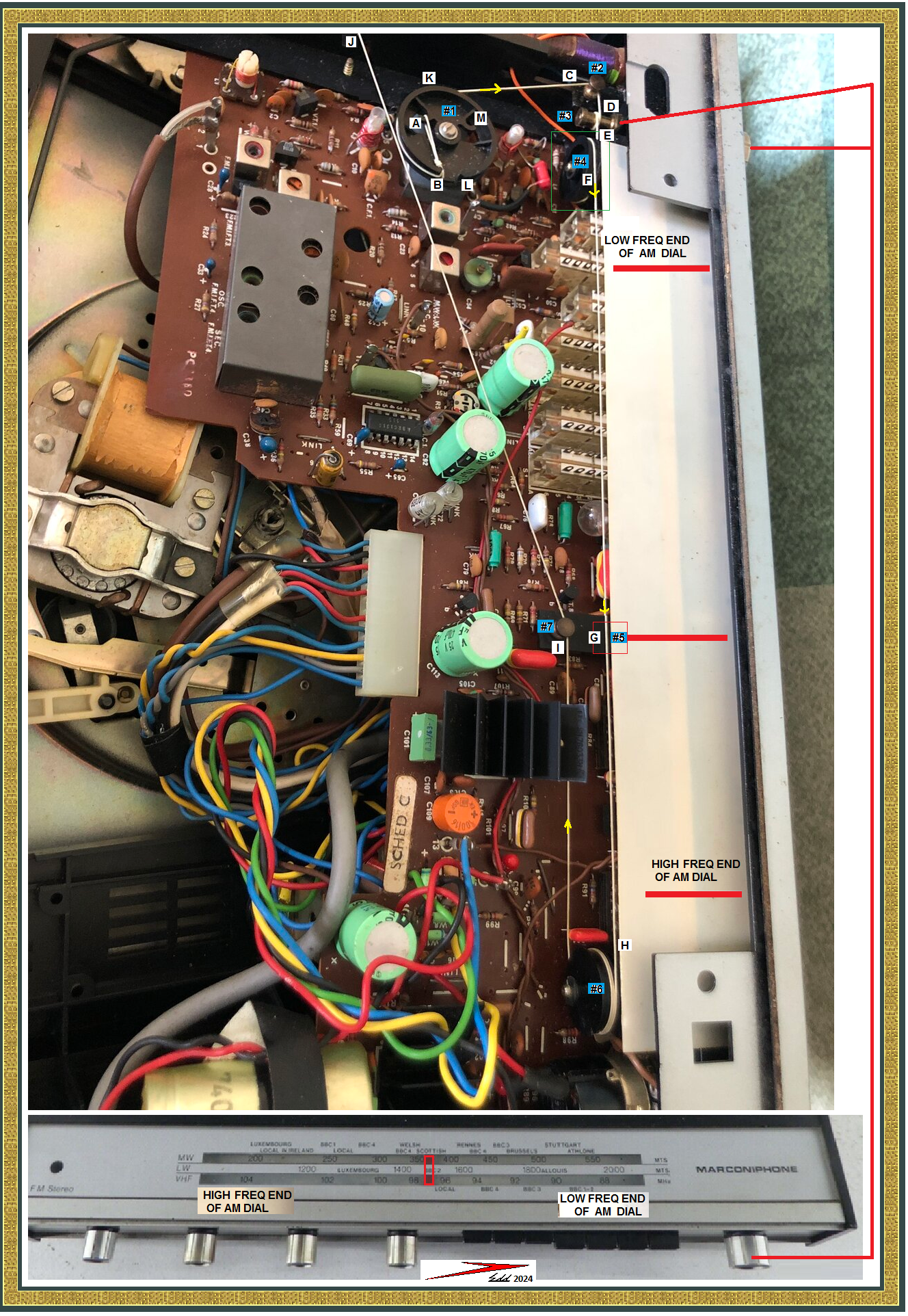
I also had to find a photo of the . . .WHOLE . . . unit, to be able to additionally see what the dial layout, and its low and high sides of the bands and what its frontal knobs functions were being.
You can see my snippet of it, being tacked onto the very bottom.
FIRST . . . . Referencing . . . . points of interest, being all marked up . . . .
On that bottom referencing of the front panel, take note of the position of the dial pointer, with its photo showing it being left at at mid scale.
Note that with the dial pointer moving to the left.
That it is tuning to higher frequency stations on the band or lower frequencies with dial movement to the right.
At far right end of the pic, the station tuning knob is being identified, an additional RED referencing line goes up to repeat its knob identification at top and its internal end as being an ~1/4 in shaft that the white dial cord wraps around. This is using 1 turn, sometimes 2 turns are used. If TOO many turns are used, the dial cord will constrict and tension excessively and roll up and fold over itself until a bit later it FLOPS back and levels out again until that repeats.
Soooooooo any flop----------flop------------flops mean excess turns have been strung onto that tuning shaft. Now with 1 turn as a minimum, I believe that present count is being correct.
Inspect that whole tuning shaft from its front to back and expect a uniform matte finish on it. Then differentiate, to see if the central dial cord path might have time developed to a centered very shiny slick surface. Like . . like . . . like the units last owner might have been ADD afflicted. With such degree of heavy use, now resulting in the cord slipping..
If encountering the latter, do not pass go . . . . .do not collect $200 . . . . do not go directly to jail, but proceed DIRECTLY . . . POST HASTE . . . to yo' Mamma Cass' boudoir and go to the dresser and acquire one each diamond dust nail file.
If encountering anyone or any resistance to your actions . . . .
SHOUT OUT ! . . . .
CHICKEN LITTLE WAS RIGHT !!!!!
Wave and hold the file high in the air and then run like hell and rush out and away to get back to your former task.
Back to work . . .
Get the tuning shaft free of its dial cord wrap, in order to then be able to place the file flat against the shaft and make a file pass from front to rear of that shaft and make the next pass adjoining to that initial pass . . . . .repeat until you have worked closely, all around the circumference of that shaft.
That should leave you with adjunct-side-by-side- linear striations completely around that tuning shaft again, thus, restoring good cord gripping actions again. Restring it again, as it was found before.
MECHANICO POINTS of INTEREST . . . .
I have used
BLUE color marker designations of dial cord transition points.
#1
BLUE Is your variable tuning condenser pulley.
#2
BLUE Is a direction change pivot point
#3
BLUE Is the end of the tuning knob shaft
#4
BLUE Is a pulley of unknown purpose at this point
#5
BLUE Is the critical /aligned/point where the traveling dial pointer gets affixed to the dial cord
#6
BLUE Is a pulley used for transition of direction of travel and repositioning of the cords exit position
#7
BLUE Is a pivot point used to have the dial cord exiting to take a fixed and defined path between two adjunct Turquoise E-caps.
You are currently left holding that tensioned cord, up at
BLACK marker
J. What'cha' gonna do ?
PERCEIVED CORDAGE ROUTING . . . . .
Let me run down the routing, using the
A-J sequential referencing points.
At hook
A in the tuning condenser you have a knotted loop engaged and then the cord is tensioned and routed down to point
B where it exits the pulley to start a clockwise wrap around that pulley periphery on up to
K and then on further up to the yellow arrow (direction of cord movement) up to
C where
BLUE #2 pivot point is getting it aligned up to then travel on the
D run and then a 1 turn wrap around the tuning knobs end of shaft and the short
E run until it has to make its wrap(s) ? around the
#4 Pulley.
(I perceive of that
BLUE #4 pulley as solely being an intermediate between
E and
F to assure a
STABLE positioned dial cord feed out into the long
F cord run, that is to then be made.)
Now note the
YELLOW arrow marker of the dial cords direction of movement.
Next landmark down, is the position that the
RED dial pointer would have transitioned into, if tuning was set to the lowest frequency station on the dial.
Now, travel further down with the dial cord and then there is a
BLUE #5 marker of the
RED dial pointer at mid scale where the unit I used the photograph of, was shown.
Also the dial cord gets affixed to the pointer by a crimp metal fold over /or/clip/or/wrap around stud /or/ glob of DUCO service cement . . .you tell us ! What is / was /previously being used there?
Next point down the dial cord path is just before
H where the dial pointer ends up when being at the very highest frequency of received stations.
From
H the cord passes to idler pulley
BLUE#6 where there is yet another direction of travel transition and cord stabilizing occurs. The cord direction of travel is now being reconfirmed with another
YELLOW arrow.
Dial cord is then passing on down to where it enters into
Blue #7 guide from position
I and then is guided to shoot between a pair of PALE- GREEN E-capacitors and then to run straight across the path to where you are now holding . . . the bag . . . . with that dial cord end at far
J.
(Gitten' tarred aren't ya ?) ( With additional, sporadic, superficial muscle spasms.)
Now lets try one test of that present dial cord run. The photo shows . . . and . . . .
OH ! . . . how close that present
I to
J cord run placement is currently being.
You presently have your initial cord exiting
B and a further wrap around the pully on to
K reference position.
NOW you take Cord end
J and hold tensioning, while moving it up just ABOVE the width of the present cord run around in the
B-K route.
It currrently vews as being just BELOW that cord position. So you now have
J cord just beside and above the other cords
B-K run and you move towards
K and past
K and come around the pulley at
M and then on to
L where you will be able to enter INTO the pulley just as you had initially passed OUT of the pulley in the
A-B dial cord route run.
Now here is where you are redy to enter into the pulley at
L but initially tension up so that the cord is taut its whole length and once you get that white cord into the pulley look over to the knot position on the
A-B run to the side. You now want to take a blue Fine tip Sharpie and make a reference mark on the cord at the
L entry point inside akin to the
B entry.knot.
This will be where you will want to make your new knot that ties into one end of the loop on the required tensioning spring.
(As was earlier mentioned by our most hon'nable,esteemed and revered
Sir Crutschow ( Esq!)
You can facilitate the dial cord J run handling while doing the " knot positioning markup" by vewy -vewy cawefully
*** using sewing thread to lash the tensioned J run cord to the left pale green vertivcal E-cap. That leaves full hands on manipulations with the then loose cord to be worked on.
Then after knot position marking, unleash the dial cord and go back to maintaining hand tension until routed and having tied a knot (s) into the spring end loop.
Ideally, the spring then pulls back and will be tensioning with 25-50% of its coils.
You can then try out the tuning knob and its present stringing to see if a full dial scale end to end travel is possible.
Also that turning the tuning knob CCW, runs the dial pointer to the left side.
NOW the big question that no availability of photos will tell me. You will have to be the informant.
This age of equipment, I am suspicioning it to be using an old school variable, air dielectric tuning condenser with metal intermeshing vanes. I am expecting the max vane pair counts to be needed for the antenna section of AM radio. A slightly smaller count for AM oscillator section .
Then there is the minute amount of smaller meshed vanes used for the FM antenna section and lastly a bit fewer count on the FM oscillattor section.
Now here is the way it will relate to dial stringing.
Look at the perspective of the tuning condenser pulley and the station pointer dial.
The
BLUE #1 pulley is now at max clockwise, to its now stopped limit of travel. The tensioned dial cord has been fed out and is traveling the YELLOW arrow path and has moved the attached
RED bar pointer to the max HIGH frequency end of the dial scale.
For this current stringing route to be correct, look and see if all of the tuning plates are in MAXIMUM un meshed positions.
Or if you then start on a movement of the tuning knob in its opposite direction ( clockwise turning). Your newly installed spring will maintain proper dial cord tensioning and the
YELLOW arrow dial cord direction will be the opposite of as before and the
RED dial scale pointer will now be moving to the right and starting to bring in low frequency end of the dial stations. Plus the vanes of the tuning condenser will be progressively meshing together. then you meet max limit travel and go back and check
RED dial pointer position to a known freq radio station and affix dial scale pointer to dial cord via supplied mode of attachment.
Then you see if the received stations are come in at the proper dial position.
BECAUSE . . . .
Since I can see that you are maintaining tension with the PRESENT dial cord run, will mean that the
C-D-E dial cord is pulling on the
Blue #1 pulley gap and the tuning condenser is being locked at its maximum of rotation limit . Also we can confirm that the cord wrap around the tuning knob and its dial cord pulling on the dial cord has rotated the dial pulley and has closed / inter meshed the plates position when at its max stop limit
Thaaaaaaaaasssit . . . . .
Now . . . .go ye forth (or fifth) and
git er done !
*** an Elmer Fudd'ism
73"s De Edd . . . . .
HAS EVERYONE GOT EVERYTHING NOW . . . . . since
I don't have any further time or enough additional boxes of CRAYONS to TOTALLY explain this to y'aal.
Any moderator . . .check out and delete my unfinished post # 5 DRAFT that timed out on me, earlier.