Hello,
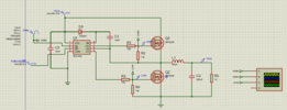
I want to test the synchronous buck converter circuit using h bridge IR2104 as mosfet gate driver. I am simulating this in Proteus 8. Here is the details of my project :
Vsupply = Up to 80V
VCC = 12V
Fsw = 39khz
Ok let’s go to the problem.
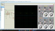
The problem is IC IR2104 is not making output PWM signal from both pin (HO & LO). From the oscilloscope, you can see signal 1 is PWM from generator, signal 2 is HO and signal 3 is LO. Did i missing something?
I want to test the synchronous buck converter circuit using h bridge IR2104 as mosfet gate driver. I am simulating this in Proteus 8. Here is the details of my project :
Vsupply = Up to 80V
VCC = 12V
Fsw = 39khz
Ok let’s go to the problem.
The problem is IC IR2104 is not making output PWM signal from both pin (HO & LO). From the oscilloscope, you can see signal 1 is PWM from generator, signal 2 is HO and signal 3 is LO. Did i missing something?