Sir gears 47 . . . . .
CHICKEN LITTLE WAS RIGHT ! . . . . . THE SKY WAS FALLING ! . . . . with a deficient discrete bridge diode and a defunct main storage cap falling
HARD onto the ground.
Now lets more fully explore, and see why the shredder motor is not running on a paper sheets entry.
Initially . . . . . with a mark up of . . . . .
PHOTO REFERENCING . . .
 or . . . .DIRECT HOT LINK
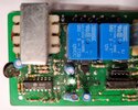
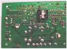
Initially, lets check out that left photo at its top and see 8 visible solder joints across the top . . . as . . . 1 space2-3-4-5 space 6 space 7 long space 8.
Now solder joint coverage on #1 looks adequate, but grab a / each wire and push in-pull out on and rotationally wiggle the wires on all of the other joints, while CLOSELY observing on the solder blob side, to confirm that there are being no floating solder joints. Do a REFLOW /REWORK with fresh solder if joints are questionable.
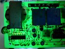
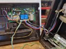
The two shades of PALE BLUE foil path markups, revealed to me that 240 VAC power goes to the left, in addition to the main power transformer PLUS your photo showing a 3 wire bi directional motor connection with assist of an AC run capacitors presence.
This means that the left mystery transformer . . . . is actually providing a reduced . . .MOST LIKELY . . . 24VAC to run the shredder motor . . . . that mystery solved.
MARKED UP PHOTOS POINTS OF INTEREST . . . .
You say . . . . .
I tested the reversing button and found that the relay near the main transformer activated and the motor ran smoothly with no relay humming noise.
I say . . . . .
So o o o o o I assigned that right side BLUE relay, as that function, leaving the other left side BLUE one as being the one that needs to be activated, in order to operate the shredder normally, after any scrap papers insertion.
Associated parts are the RED star, back EMF quenching diodes are across each relays coil.
Take note of the GREEN and BLUE rectangle marked relay driver transistors facing each other. I HIGHLY suspicion that each transistors required individual base drive is coming in from each of the two separate 4.7k resistors.
I also marked them in on the FOIL photo to the left. Blue and Green connecting lines go from resistors to bases on the right photo. Other transistor element connections fall into place, with my suspicion of the transistor center pin being collector and going to its relay coil, with the transistors far end pin being emitter and going to ground.
Will you positively confirm this for me ! ***
POWER SUPPLY MARKUPS . . .
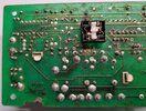
VERY top input is constant 240VAC to power transformer primary if the units master power switch is on.
Secondary AC from transformer goes into discrete 4 diode FWB at central diode points and is DC collected at left ends
Red + rectangle and right ends
Black - rectangle and sent to your NEW 220 ufd main E-storage cap.
12VDC also passes to far right to 3 terminal +5VDC regulator and routes back as +5VDC regulated at smaller BLUE E-cap, just below the earlier MAIN one.
If there was no insulator used at the 3 term regulator, its finned heat sink might be more convenient to clip a meter ground lead onto, instead of the FWB - diode lead pairs.
THE OPTICAL INTERRUPTER PAIR . . . .
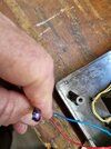
YOU PUT A PAPER INTO THE FRONTAL SLOT FAR ENOUGH, THAT THE PAPER THEN BLOCKS THE LED to SENSOR BEAM AND THE SHREDDER MOTOR ACTIVATES AND PULLS IT IN FOR SHREDDING.
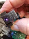
One of your photos has shown us an operational LED emitter. Circuit wise, its having a . . . . 12? or 5 ? VDC supply passing thru a voltage dropping / current limiting supply resistor to the LED and the other LED lead to ground.
But now, we don't know if the other half's . . . . receptor / sensor. . . . is being an active or passive unit .
E.G. . . . being . . . self voltage generating, like a solar cell . . . . . . . . or variable resistive, like a CdS cell.
We would expect one receptor / sensor lead to be grounded also.
Look at the 4 Pin connector that the optical interrupters pair of wires connect into, its location is being sandwiched between the discrete FWB diodes and the 74LS02 logic chip. I have already assigned 4 random numbers to it.
With a dead and un powered shredder unit, take ohmmeter in hand in its lowest ohm range and short probes together to take a dead short reading. Take note. Move to then ohmically testing between FWB diode negative pairs and the finned heat sink of the regulator, is there also almost 0 ohms there ? if so, the regulators finned heat sink is a viable alternate meter negative grounding connection also.
Now lets move back to the optical-interrupter pair and keep of the ohmmeters probes on ground ad see if 2 of those 4 pins are ground connected ? Report back.
Next look at the small resistor just to the right of pin 4 of that connector. In that boards linear layout . . . .isn't it logical ? foil flow path sequence such that the right resistor lead goes to +5 or +12 VDC power supply and the left
resistor lead feeds the pin to the LED emitter, with the LED's other lead being grounded. Sort of expecting pin #4 to be receiving voltage reduced and current limited power and pin #3 to be grounded .
OF COURSE . . . . You already have visual confirmation of the wire color coding of the 2 wire pairs connecting pins.
That then leaves pins #1 and #2 to relate to the sensor connections, if one of those pins has already identified as being grounded then the other has to be the "active " connection.
Then we have an UBER HIGH interest, in the sequential circuit routing of that "active" voltage level thru the TTL and linear circuitry, until it finally provides base drive to the GREEN relay driver transistor-close relay-run shredder motor.
FIRST POWER UP ANALYTICAL TESTING . . . . .
Place meter negative test lead to a confirmed ground and then set to + DC Volts range . . .expecting <20VDC . . . .+ meter probe goes to right resistor lead of the resistor just to the right of 4 pin O-I connector.
What is that supply voltage ? then what is the voltage to the left lead of that resistor . . . .establishing Emitter LED Vf run spec.
Next points of interest would be the received base drive levels of the two relay driver BLUE and GREEN transistors.
Examine the left photo and see your now exposed RED paper jam electro-mechanical switch, it appears to have a left and right pole piece and a fixed single contact for each movable pole, thus making it a
Double Pole Single Throw unit. On the left photo, just to the switches left, I have a vertically drawn in 4.7k resistor . . . also its ACTUALLY being present on the right photo.
Now what we want to do is use the same DC metering set up as was just used before.
We want a power up and take measurement of the DC voltage level in at the bottom lead of that 4.7k resistor . . .log down . . . and then on the top lead of that resistor. . . log down.
NOW monitor the bottom supply side of that resistor and press the RED switch and start reverse motor action and see if that voltage level pulls down, if so, log down.
Release the RED switch and move metering to the top lead of that resistor and log down its voltage supplied to the Blue transistors base.
Now press the RED switch an see what that voltage changes to log down and then hold the RED button down again to see if the lower leads supply voltage was pulled down, if so, log it down.
You now have some idea of voltage changes involved with the functioning Blue driver circuitry.
NOW . . .lets move up to the Green driver circuitry and see whats being amiss in that non working section.
Go thru the same testing sequence in monitoring across that twin 4.7k up at the Green line input to the base of the Green relay driver transistor.
The EXCEPTION / VARIANCE , this time will be the need to use an opaque piece of cardboard just inserted enough to block the beam of the photo-interruptor path instead the prior Red switch.
Initially take power in 4.7k resistor lead reading and also base of transistor lead readings and then just block the beam and take the same readings to see what the base drive voltage is being and if the supply side of the resistor pulls down and log down voltages.
You confirmed what was needed on the other working transistors base for relay activation. What voltage level is now being present on the inoperative Green driver stage ?
Finally monitor the left side of the resistors left end lead and then use the cardboard to block and unblock the beam to see if there is the synchronous response of an according . . . . . even slightest up and down voltage change.
If not, we will next be off on a sequential logic trail hunt.
BREAK-A-BREAK-A TIME . . . . .
To see if additional info is needed . . .feed back of voltage readings . . . . your answers
73's de Edd . . . . .
 01_showing connected motor to board.jpg194.7 KB · Views: 14
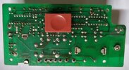 02_Bottom circuit board showing reversing switch.jpg83.7 KB · Views: 14
 07_Bottom of board with voltage readings.jpg88 KB · Views: 13
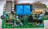 04_Top of circuit board showing auto start_stop connection point.jpg200.9 KB · Views: 14
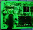
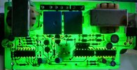 05_Top of board with light behind.jpg196.2 KB · Views: 12
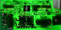 06_Bottom of board with light behind.jpg99.1 KB · Views: 10
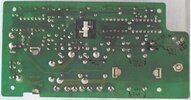 07_Bottom of board with voltage readings.jpg88 KB · Views: 11