Maker Pro
Maker Pro

PCB reference designator question / iding a component

tt500pilot

Apr 17, 2009
4
Joined
Apr 17, 2009
Messages
4
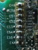
I have a motor control board with PIC driving an HC595A that is driving a uln2003 that in turn is controling 7 relays that activate various motors. Attached to each output of the uln2003 is an sms component wired in series with the coil (-) that has a PCB reference designator starting with an "E". Can someone tell me what these components are ? There are no markings on the actual device. The "E" is on the PBC. ie: E49,E50,E51,etc...
 

CocaCola

Apr 7, 2012
3,635
Joined
Apr 7, 2012
Messages
3,635
Pictures? Also are you sure it's in series and not parallel to the relay? If it's parallel it's likely a fly back diode, in series might be a resistor, a pictures would certainly help in identification...
 

tt500pilot

Apr 17, 2009
4
Joined
Apr 17, 2009
Messages
4
Pictures? Also are you sure it's in series and not parallel to the relay? If it's parallel it's likely a fly back diode, in series might be a resistor, a pictures would certainly help in identification...

Definitely wired in series. the pads to the right of the"E"'s are where the uln2003 used to be. The lands to the right goto the coil (-). Continuity between both ends of the component both ways.
 

Attachments

  • IMG_0038.jpg
    IMG_0038.jpg
    151.4 KB · Views: 601

CocaCola

Apr 7, 2012
3,635
Joined
Apr 7, 2012
Messages
3,635
They might just be shunts that enable or disable features? You can see another larger shunt in the bottom right corner identified with 000, so the use of other shunts on this design is quiet possible...
 

tt500pilot

Apr 17, 2009
4
Joined
Apr 17, 2009
Messages
4
They might just be shunts that enable or disable features? You can see another larger shunt in the bottom right corner identified with 000, so the use of other shunts on this design is quiet possible...[/QUOT]


Makes sense although on the uln2003 they had two of these in series with Pin 9 (common) and two in series with pin 8 (Ground) ... all four of these expired when the board failed due to a neearby lightening strike. Why would they put two shunts in series with each of these pins ?The designer did use them elsewhere on the board . Is there a standard that specifies what an "E" component is ?
 

CocaCola

Apr 7, 2012
3,635
Joined
Apr 7, 2012
Messages
3,635
There is no 'standard' that anyone really follows when it comes to PC board silk screens, but there are some standards that some will follow... If one is to follow the common trend E would indicate a terminal...

As for why there may be several in series, look at the PC board layout, the might have used them as an additional layer to accomplish the layout without bumping up the actual PC board layer count...

This is only speculation...

table-1-standard-ref-des-for-schematic-symbols.png


http://s3-blogs.mentor.com/tom-haus...-1-standard-ref-des-for-schematic-symbols.png
 

gorgon

Jun 6, 2011
603
Joined
Jun 6, 2011
Messages
603
Do you know where the PCB is coming from? Which country, nationality? Could it be a language problem?

TOK ;)
 

tt500pilot

Apr 17, 2009
4
Joined
Apr 17, 2009
Messages
4
Do you know where the PCB is coming from? Which country, nationality? Could it be a language problem?

TOK ;)

It's a Gecko Spa Controller card and everything on it is in English.. but not sure where it was manufactured. It looks like the PCB designer decided to use these components wherever one might want to test the current flow.. so I think CocaCola's suggestion that these maybe very low value resistors/shunts may have solved the mystery. They measure about 0.3 - 0.4 ohms using my EX520.
 

davenn

Moderator
Sep 5, 2009
14,271
Joined
Sep 5, 2009
Messages
14,271
They look just small inductors often seen in such places

Dave
 
Top