Maker Pro
Maker Pro

Reading value from Solar Panel Cell, current peak concern

ge96

Sep 23, 2017
30
Joined
Sep 23, 2017
Messages
30
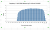
I just setup a Raspberry Pi to read the voltage being produced from a Solar Panel using an MCP3008 and following Adafruit's tutorials.

Anyway, one concern from the data sheet is that the ADC can operate max with 5V 500 micro amps.

If I'm reading it right (and so far ADC is still working) currently the solar cell indoors (under yellow incandescent light) is producing 1.49V at 70 micro amps. The solar cell is rated for 5V at 100 milli amps

What do I do when it actually gets sunlight and gets past 500 micro amps?

I think I'm supposed to use a 10K resistor, but I'm not sure what that means with regard to the measured voltage...

V = IR

but I don't know what that means with respect to the context

Right now when taking the two values 1.49V at 0.00007A = ~ 21.3K Ohms... what does that mean? Is that right?

So with regard to limiting the current to a max of say 300 micro amps "to be safe" what do I need to do? (read some books) haha

Thanks for any help
 

ge96

Sep 23, 2017
30
Joined
Sep 23, 2017
Messages
30
So I completely misunderstood how this works... that was the draw from the ADC and does not concern the "current output" of the solar panel which needs a load...I don't know I think I'm okay.
 

(*steve*)

¡sǝpodᴉʇuɐ ǝɥʇ ɹɐǝɥd
Moderator
Jan 21, 2010
25,510
Joined
Jan 21, 2010
Messages
25,510
I think you're right, but what are you trying to do? I'm curious as to why you're reading the voltage on a solar panel (not a criticism).
 

ge96

Sep 23, 2017
30
Joined
Sep 23, 2017
Messages
30
I think you're right, but what are you trying to do? I'm curious as to why you're reading the voltage on a solar panel (not a criticism).

Nothing yet, I'm more on the "code" side coming in as a web developer. Right now I'm just trying to do a solar plotter, it just grabs samples from the day (voltage measured from panel) and then sends it to a website and creates a chart.

But I'm trying to get more into the hard ware side and eventually work on a charger, for small application like a 2 cell lipo or Li-ion a123 cells.

But yeah... at least I'm working with a hardware person.
 

(*steve*)

¡sǝpodᴉʇuɐ ǝɥʇ ɹɐǝɥd
Moderator
Jan 21, 2010
25,510
Joined
Jan 21, 2010
Messages
25,510
That's fine, but the voltage you read from a solar panel will reach a maximum well before you get to a level of illumination where the power available from the panel reaches it's nominal rating.
 

ge96

Sep 23, 2017
30
Joined
Sep 23, 2017
Messages
30
That's fine, but the voltage you read from a solar panel will reach a maximum well before you get to a level of illumination where the power available from the panel reaches it's nominal rating.

Sorry I don't understand?

"a level of illumination" what do you mean by this?

I'm just trying to get the voltage coming from the panel, it seems to be correct, with reference to a multimeter, measuring in the same spot/source eg. house light.

At this time I'm not really trying to do anything with the power coming from the panel, just measure the voltage.
 

(*steve*)

¡sǝpodᴉʇuɐ ǝɥʇ ɹɐǝɥd
Moderator
Jan 21, 2010
25,510
Joined
Jan 21, 2010
Messages
25,510
It's ok. You're not trying to measure power or something like that.
 

ge96

Sep 23, 2017
30
Joined
Sep 23, 2017
Messages
30
It's ok. You're not trying to measure power or something like that.

Actually I may understand what you're saying. The sun is barely up and it's already almost 5V. I don't know if the power measurement would have a larger growth/gradient or if this is normal.

My solar cell is orthogonal from the path of the sun rising, currently the sun I'd say is 15 degrees up from the horizon.

I was hoping to plot a nice bell curve against V/P vs. Time but it's already peaked in the first "sun rise hour"
 

(*steve*)

¡sǝpodᴉʇuɐ ǝɥʇ ɹɐǝɥd
Moderator
Jan 21, 2010
25,510
Joined
Jan 21, 2010
Messages
25,510
Yep, that's kinda what you should expect.

Put a 50Ω 1W resistor across the solar panel and you should get something better.
 

hevans1944

Hop - AC8NS
Jun 21, 2012
4,891
Joined
Jun 21, 2012
Messages
4,891
Go read the paper that won Albert Einstein his Nobel Prize. Or read about it if you don't read German.

Photo-voltaic cells produce a voltage output that is a function only of the wavelength of light to which they are exposed. They produce a current into a load resistance that is a function of how intense the light is and the electrical resistance of the load attached to the cell. You will need to load your photo-voltaic panel with a resistance to obtain your "bell-like" curve of output versus time during the day.

If you are concerned with measuring cell performance or efficiency, you will need to know the internal resistance of the cell or panel. The internal resistance appears in series with the output and causes the terminal voltage of the cell or panel to decrease as the current drawn from the cell or panel increases. There will be a particular load resistance that results in maximum power transfer from the photo-voltaic cell or panel to the load resistance. Many alternative energy systems try to adapt their load resistance to maximize the power sourced from their photo-voltaic panels. How this is accomplished is interesting, but beyond the scope of this reply.
 

ge96

Sep 23, 2017
30
Joined
Sep 23, 2017
Messages
30
Yep, that's kinda what you should expect.

Put a 50Ω 1W resistor across the solar panel and you should get something better.


Yeah it's just peaked around 4.7V sun is really bright now at 10:30 AM central US time

I'll give that a shot thanks for the suggestion
 

ge96

Sep 23, 2017
30
Joined
Sep 23, 2017
Messages
30
Meant to partially quote you but the delete backspace.... Anyway

Thank you for the information I will take a closer look at this once I'm out of work.

Yeah I'm after the bell curve, not sure if it makes sense to expect it.

Thanks for the suggestion about the Albert Einstein paper, I can't read German so will read about it.
 

ge96

Sep 23, 2017
30
Joined
Sep 23, 2017
Messages
30
@ge96: To save you some time, go look at this Google results page.

It's a shame that I was actually a physics major and took E&M a few years back, I do.n't know, you don't use it forget it.

Edit: I'm not sure which branch it falls inder actually. Compton scattering... Lorentz... The one cool lab was the bending of a stream of electrons going through a uniform magnetic field (orthogonal) it was a in sealed tube and you could see the beam light up and bend by the intensity of the magnetic field or the other variable. Right hand rule yo! I don't know... Sucks but decisions in life I guess.

Calculating the speed of light, using an interferometer to disprove the existence of ether. Ahh good labs

Thanks
 
Last edited:

hevans1944

Hop - AC8NS
Jun 21, 2012
4,891
Joined
Jun 21, 2012
Messages
4,891
@ge96: I am sorry that I misled you in suggesting photo-voltaic output voltage is a function of illumination wavelength. This applies only to photo-electrons emitted from metals in a vacuum. For a silicon PV cell It is a function of the band-gap of the semiconductor materials used to the form the PN photo-voltaic junction. Any wavelength shorter than is necessary to create an electron-hole pair (the band-gap energy) will just add thermal energy to the electron-hole pair and accomplish nothing useful. Here is a Wikipedia article that explains this more or less in layman's terms...

Yeah, I am forgetting a lot of stuff lately, but I chalk it up to 'alt timer's disease... as in "Hey, 'alt timer, do you remember where you parked your car today? What you had for breakfast? For lunch? What day it is?" Heh. Trying all sorts of "brain boosting" OTC remedies, but not sure if any of those pills are helping.
 

ge96

Sep 23, 2017
30
Joined
Sep 23, 2017
Messages
30
Yeah, I am forgetting a lot of stuff lately, but I chalk it up to 'alt timer's disease... as in "Hey, 'alt timer, do you remember where you parked your car today? What you had for breakfast? For lunch? What day it is?" Heh. Trying all sorts of "brain boosting" OTC remedies, but not sure if any of those pills are helping.

With how easy it is to open up Google and research... For me I keep looking up the same thing over and over again like the order of an explode method (the string to be split, or the substring splitter), and others but long as you get the job done I guess.

Anyway hopefully I get this figured out and improved. Then I get to make pretty daily charts for each day.
 

(*steve*)

¡sǝpodᴉʇuɐ ǝɥʇ ɹɐǝɥd
Moderator
Jan 21, 2010
25,510
Joined
Jan 21, 2010
Messages
25,510
You may find that you get prettier bell shaped graphs of you measure max power from the solar panel. Unfortunately that is significantly more difficult.

I think it's best you try out the simple method first and see what results you get. If you find they're a bit pointy, we can talk about what you need to do to measure maximum power.
 

ge96

Sep 23, 2017
30
Joined
Sep 23, 2017
Messages
30
You may find that you get prettier bell shaped graphs of you measure max power from the solar panel. Unfortunately that is significantly more difficult.

I think it's best you try out the simple method first and see what results you get. If you find they're a bit pointy, we can talk about what you need to do to measure maximum power.

This doesn't look too bad... I'm not registering yet right now how to use the time as the x-axis, I recorded "human format" eg. hh:mm am/pm... wondering if I should use epoch or something... maybe turn it all into minutes or something... where you can see the increment

Anyway here is a chart, I grabbed about 112 samples (last 5 were from new day) (or attached if not inline)

You can see a bell-ish shape

I'm going to try what you mentioned

Put a 50Ω 1W resistor across the solar panel and you should get something better.

I'm not sure that literally reads 50 Ohms right? Not K ohms? The lowest that I have lying around is supposed to be 220 ohms but measuring it reads as 330 ohms. Anyway I found that bumping it up to 50K Ohm worked best... I don't seem to have anything that is 1W rated. I don't know how to tell unless reading from a spec sheet, from the brief search the 50K B potentiometer that I have is supposedly rated at just 0.2W which if I did the 0.1A * 5V = 0.5W... could produce more than the pot is rated for... I added a 10K resistor as a wire (tuned the pot to 40 KOhms)

Ah these are 1/4 watt resistors... so 2 in parallel... oh man I did this before... one of them I think for series it's adding fractions... hmm nope parallel is divide... so series.

I could do 4 x 10 Ohm 1/4 watt would become... 40 Ohm 1 Watt? oh and the dissipation part too... well I'll start recording, will sleep/see what happens. Wake up to a fire. haha MY LEGS ARE ON FIRE!!! AHHH

initial ramblings
https://pastebin.com/ye4ZYTcD
 

Attachments

  • 09-23-2014-samples.png
    09-23-2014-samples.png
    21 KB · Views: 143

ge96

Sep 23, 2017
30
Joined
Sep 23, 2017
Messages
30
Well that was completely wrong about the four resistors in series to "increase wattage"

Luckily my friend has a 1W LED... so just gotta figure out... this wasn't a trick question right? No... need to add a resistor to the LED for something. Panel at best can produce 4.8V * 0.1A (measured voltage from sun) and specified current... ~ 0.48 A so if the LED wants to use 1W... it will just keep trying to pull power from the Solar Panel that's the goal? Jesus like talking to a brick (me). Man... I guess I do remember the first time I started building HTML pages and could barely build a UI that I could draw on paper.

Data sheet says working current is 200-350mA

Ding ding... I think I've got it, I can put the.. ohh... lowest I have is 330 Ohm ~d

So yeah that's what I actually have plugged in now to get values off of "Here comes the sun Beatles" waiting for it

1 220 Ohm resistor in front of the 1W LED and then it goes into the ADC channel (read), getting values out but it's dark

spec sheet on 1W LED, I'm assuming it's this one
https://cdn-shop.adafruit.com/datasheets/BL-HP20AxxxL.pdf
 

(*steve*)

¡sǝpodᴉʇuɐ ǝɥʇ ɹɐǝɥd
Moderator
Jan 21, 2010
25,510
Joined
Jan 21, 2010
Messages
25,510
Yes, 4 x 1/4W resistors will allow you to dissipate 1W. You DEFINITELY don't want a LED in there.

If you have 6 or 7 330 ohm resistors, place them in parallel. You'll get a resistance close enough to 50 ohms for this purpose and it will be able to handle the power.
 
Top