Maker Pro
Maker Pro

Reading value from Solar Panel Cell, current peak concern

hevans1944

Hop - AC8NS
Jun 21, 2012
4,891
Joined
Jun 21, 2012
Messages
4,891
I guess I do remember the first time I started building HTML pages and could barely build a UI that I could draw on paper.
I am impressed that you were able to write code that sent data from your RPi to a URL website address and then display that data as a graph for screen capture. Hmm. Does anyone still write native HTML to build web pages anymore? I thought this sort of thing was now down by "script kiddies" using a commercial app that creates web pages, and whose only familiarity with HTML was the four initial letters of Hyper Text Markup Language.

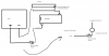
You may have a misunderstanding of how to load your solar panel. Think of it as a battery with a positive terminal and a negative terminal. The negative terminal connects to the common (or ground) of the RPi. The load is any resistance, including the input resistance of the ADC, connected between the positive terminal and the negative terminal, otherwise known as common or ground. If you connect a resistor to the positive terminal, and in series with the anode of an LED, and then connect the cathode of the LED to the input of the ADC the relatively high input resistance of the ADC will dominate this circuit, providing almost no load on the photovoltaic panel. You need to connect the LED cathode to the negative terminal, thus providing a load on the solar panel. Then measure the solar panel terminal voltage between the positive terminal and the negative (common or ground) terminal.

You don't actually NEED an LED to load the solar panel. Resistors will work just fine. If you use a 50Ω resistor and the panel produces 5V on a bright, sun-shiny, day then a current of 5/50 = 0.1 A will be drawn from the panel and dissipated as 0.5 watts of heat in the resistor. The ADC will draw a comparatively insignificant amount of current from the panel to measure the 5V output.

Power dissipated in resistors is additive, whether resistors are connected in series, in parallel, or a combination of series and parallel. You do need to calculate the power in each resistor, which will depend on their values and how they are connected to the source of power, but the sum of the power in each resistor all add up to the total power dissipated. If all the resistors are the same value, the calculations are somewhat simplified. For example, ten quarter-watt resistors, all of the same value, will dissipate 2.5 watts whether you connect them in series or in parallel, or any combination of series and parallel, but some combinations may result in more than a quarter-watt dissipation for a particular resistor, so you need to be careful. If you have, say, ten resistors of 100Ω each connected in series, the total resistance is 1000Ω. To dissipate 2.5 watts, that series string will need 50V applied to it and this will result in a current of 50/1000 = 0.05 A in each resistor. This current will then dissipate I²R watts = 0.25 W in each of the 100Ω resistors.

If the ten 100Ω resistors are connected in parallel, instead of in series, the total resistance will be 10Ω and require only 5V to dissipate 2.5 watts with a current of 0.5 A, but each resistor will still only dissipate 0.25 W because the total current is equally divided among ten 10Ω resistors (0.05 A per resistor) resulting in a power of I²R watts = 0.25 W in each of the 100Ω resistors.
 
Last edited:

ge96

Sep 23, 2017
30
Joined
Sep 23, 2017
Messages
30
Yes, 4 x 1/4W resistors will allow you to dissipate 1W. You DEFINITELY don't want a LED in there.

If you have 6 or 7 330 ohm resistors, place them in parallel. You'll get a resistance close enough to 50 ohms for this purpose and it will be able to handle the power.

It's a 1W LED though? Good to know about the 6 or 7 330ohm resistors, I do have 10 of them from the kit so I will try that.

Unfortunately my public IP changed (damn DHCP) so it's one of the checks to my crappy url post and all the data stopped recording at 6 AM, after I fixed it though I see a difference between yesterday and today.

At 1:50 PM yesterday it recorded 4.82 V and today it recorded 2.89 V it is cloudy though yesterday hardly cloudy
 

ge96

Sep 23, 2017
30
Joined
Sep 23, 2017
Messages
30
I am impressed that you were able to write code that sent data from your RPi to a URL website address and then display that data as a graph for screen capture. Hmm. Does anyone still write native HTML to build web pages anymore? I thought this sort of thing was now down by "script kiddies" using a commercial app that creates web pages, and whose only familiarity with HTML was the four initial letters of Hyper Text Markup Language.

Yeah I myself am behind in the webdev world, trying to catch up working with databases other than mysql, trying to learn a framework, but have to use it to learn it. With python I just started to use it but have been using PHP/JavaScript for a while. And with actual things I want to do it helps.

Yeah I didn't really create a "legit API" that's something I'm still trying to figure out because of the Cross origin (CORs problem) that prevents you from sending a request to another domain... unless you allow it/configure it.

I made it by requesting a url built with the parameters and then putting some security features like keys and ip... it's not great... but works for now. The graphing part I did it manually last night (with LibreOffice calc think Word Excel), but I want to use something called d3.js which I have been hearing a lot about to make the charts.

I've got the data outputting live here, but you can see (if you happen to look at this at 2 PM central) it stopped because of the public ip change from my home

http://raspisolarplotter.com/

I gotta update that ip check with another key. Ahh, apparently our internet went down for a bit and the ip changed, it hasn't changed in possibly months so... but maybe I was only remembering the first two octets.

If you connect a resistor to the positive terminal, and in series with the anode of an LED, and then connect the cathode of the LED to the input of the ADC the relatively high input resistance of the ADC will dominate this circuit, providing almost no load on the photovoltaic panel. You need to connect the LED cathode to the negative terminal, thus providing a load on the solar panel. Then measure the solar panel terminal voltage between the positive terminal and the negative (common or ground) terminal.

I think I get what you're saying (pictures) I think I currently have the first version where the positive part of the LED is connected to the resistor and then the negative part of the LED goes into the ADC input.

I'm using the LED because of the "1W" part but I guess I got that wrong if this thing has no resistance. So yeah I'll probably do the 6 or 7 220ohm resistor in parallel as mentioned by Steve as all my resistors are 1/4 watt.

I don't have a resistor that low, lowest I have is 220 ohm but going off your 5/50 = 0.1 A will be drawn, I could do 5/330 = 0.015 A, I think even one resistor (quarter watt) will work then right?

Wow with just one 330 ohm resistor the value measured is high (highest it's been) and it's cloudy today. It is more stable the output consistently first two numbers are the same eg. 958, 958, 957, etc... The LED and resistor in series that I had used a 330 ohm resistor... so for it to drop to the 500's (2.7v range) wondering is that the LED doing that? Keep in mind it's not a cliche red LED it's a "High Power LED"

Thanks for the two paragraphs of examples, I will have to re-read it a few times/think about what I should do.

I think today's data sampling is not good anyway with the outage.

I'm not sure if just one resistor is enough of a load to get the nice data. I should probably know just from what you guys have said already.

I doodled a crappy paint image to show what I have setup right now. (just the one resistor) the resistor isn't hot though so I guess it's cool... ? haha ah man
 

Attachments

  • current-wiring.png
    current-wiring.png
    23.1 KB · Views: 78
Last edited:

ge96

Sep 23, 2017
30
Joined
Sep 23, 2017
Messages
30
Yeah I'm not sure why I'm having a hard time understand this section of your response @ hevans1944

If you connect a resistor to the positive terminal, and in series with the anode of an LED, and then connect the cathode of the LED to the input of the ADC the relatively high input resistance of the ADC will dominate this circuit, providing almost no load on the photovoltaic panel. You need to connect the LED cathode to the negative terminal, thus providing a load on the solar panel.

I did the initial described method because I figured the LED had a polarity so it should have the + end connected to the positive end of the photo cell output right? (as in my wiring drawing above)

Maybe I get it, I actually got the LED to turn on, it requires I think at least 2V or so to turn on. Seems "ironic"? Powering a light with light...

This is the updated circuit then and now the analog readout is back down to the 500's with a 5V reference.

One on the left is current with LED negative connected to ground, then before that or on same line of positive side of LED goes into ADC to measure the panel if I got that right.

Now it seems on a cloudy day but still sunny I'm measuring 2.67V at this sample
 

Attachments

  • new-vs-old.png
    new-vs-old.png
    307.3 KB · Views: 113

BobK

Jan 5, 2010
7,682
Joined
Jan 5, 2010
Messages
7,682
Your diagram does not make any sense to me. The MCP3008 should not be in series with the load!

Are those supposed to be pins 1, and 9 of the MCP3008? If not, what pins are they?

bob
 

ge96

Sep 23, 2017
30
Joined
Sep 23, 2017
Messages
30
Your diagram does not make any sense to me. The MCP3008 should not be in series with the load!

Are those supposed to be pins 1, and 9 of the MCP3008? If not, what pins are they?

bob

Yeah sorry the diagram is pretty bad. The half circle on tbe ADC is the top, from my diagram the bottom left of the ADC is ch0 out of (0-7)

Yeah initially it was in series with the load and the LED wasn't on, not sure if I was within spec with regard to nothing breaking. I have more unused ADC's I could test to see if I damaged the ADC.

I have since switched the wiring. The pos conctact of the LED shares a rail going into the ADC but the LED neg end goes into the goes into neg rail shared by the adc.

This photo is not good it's just what I have on hand.

The pi isn't obvious my friend printed a case for it, I wanted it to be a socket-server plugged into a socket like a wall adapter but it wasn't finished and I soldered some female headers into a 90 degree thing to still have access to the GPIO despite the pi being primarily a web server.

Edit: the +/- tape on the bread board aren't current they were crom before when I was wiring the LCD for ip display initially.

This was from a really cheap arduino kit, the instructions say 220 ohm res but they're actually 330 not complaining as it was a gift.
 

Attachments

  • 20170924_145354.jpg
    20170924_145354.jpg
    152.8 KB · Views: 106

hevans1944

Hop - AC8NS
Jun 21, 2012
4,891
Joined
Jun 21, 2012
Messages
4,891
You mentioned in post #1:

If I'm reading it right (and so far ADC is still working) currently the solar cell indoors (under yellow incandescent light) is producing 1.49V at 70 micro amps. The solar cell is rated for 5V at 100 milli amps
So how did you "measure" that the solar cell was producing 1.49V at 70 micro amps? Did you place a load resistor of about 21.3 kΩ across the solar panel terminals, and then measure 1.49 V across that resistor under incandescent room lighting conditions? If so, there would indeed be 70 μA current in this load resistor. If you then took the solar panel outside, exposing it perpendicular to the direct rays of the Sun at HIgh Noon in Indiana (HNI), and measured its output voltage as 5 V, then the current through your 21.3 kΩ load resistor would increase to about 0.002 A. This is a far cry from the 100 mA rated output of the solar panel. Only about one milliwatt of power would dissipate in the resistor. The maximum output power from the panel is 5 V at 100 mA, or 0.5 watts. Assuming negligible internal resistance of the solar cell array (NOT a good assumption, but okay for this "ballpark" estimation), then a load resistance of 50 Ω would draw 100 mA with 5 V solar panel voltage and this load would dissipate 0.5 watts. Your 330 Ω resistors (just one of them), placed as a load across the solar panel output, would draw at HNI 5 V/330 Ω = 0.015 A and dissipate about 0.076 watts, clearly well within their 0.25 watt rating.

Your MCP3008 ADC channel input needs to be connected in parallel (not series) with whatever load resistance you place across the output terminals of your solar panel. If you cannot get your head around this idea, there is nothing more we can do here to help you. Suggest you read an Electricity for Dummies text for review of basic circuit principles.
 

ge96

Sep 23, 2017
30
Joined
Sep 23, 2017
Messages
30
The measure was probably dumb, I measured it with a multimeter being aware at least of the multimeter's max current limit but measuring it without load/not being exposed to real light probably means the measurement is useless.

No resistor just direct output leads from solar cell.

I believe it is currently in parallel layout at this time. But yeah, not a bad idea to go read.

Anyway thanks for both of your time.
 

hevans1944

Hop - AC8NS
Jun 21, 2012
4,891
Joined
Jun 21, 2012
Messages
4,891
The measure was probably dumb, I measured it with a multimeter being aware at least of the multimeter's max current limit but measuring it without load/not being exposed to real light probably means the measurement is useless. ...
There is no such thing as a dumb measurement. Dumbness creeps in when you wrongly interpret the result of the measurement. And there is no such thing as "real light" versus whatever you think the alternative is. Light just IS and the solar cell array works just fine using incandescent illumination from a light bulb or radiation from the Sun. The only thing that changes is the conversion efficiency and the amount of power produced by the light being converted to electricity.

Your multimeter has TWO ways to measure the output of the solar cell array panel: voltage mode and current mode. In voltage mode, it draws almost no current from the solar panel. That is what voltmeters are supposed to do: measure voltage without drawing any current in doing so. Of course real voltage measurements DO draw some current, but for your multimeter and this solar cell panel the current can probably be considered to be negligible. Same applies to your MCP3008 Analog to Digital Converter chip. It has a high input resistance and presents a negligible load to the solar panel.

In current mode your multimeter ideally looks like a short circuit, so no voltage is developed across the test leads when measuring current. That is what ammeters are supposed to do: measure current without imposing a voltage drop across the meter terminals, connected in series with the load, in doing so. Of course real current measurements place SOME voltage burden on the source of the current, typically a few millivolts or a few microvolts. This burden subtracts from the open-circuit terminal voltage of the current source when you measure the current.

It is likely that if you used the multimeter in current mode on a sensitive range, say, 100 micro-amperes full scale, and measured 70 μA with the solar panel illuminated only with incandescent room lighting you would find the solar panel terminal voltage to be close to zero volts (instead of 1.49 V) when you made this current measurement. Of course you would need a SECOND multimeter, placed in parallel across the solar panel output terminals to make this voltage measurement, while the first (current mode) meter would be placed directly across the solar panel output, also essentially in parallel with the first meter, but also in series with the solar panel output.

Measuring the open-circuit voltage and the short-circuit current produced by a solar panel provides a rough estimate of how much power it can deliver to an electrical load, say for charging a battery. You can even take these two measurements outside on a HNI sunny day without fear of damaging either meter or solar panel. Once a certain intensity of illumination is achieved, the open-circuit panel voltage will be a steady 5 V and will not vary much during the day. The short-circuit current, OTOH, will vary linearly with illumination intensity. This short-circuit current is what you should be measuring with your MCP3008 ADC chip if you want to record changes in solar panel output from dawn to dusk.

Problem is, the MCP3008 ADC has a fairly high input resistance... it doesn't provide much of a load on the solar panel output, much less approximate anything close to a short-circuit current measurement. So when you connect the input channel and common of the ADC to the positive and negative terminals of the solar panel, you are essentially measuring the open-circuit (no load) output voltage. Shortly after dawn this will peak at about 5 V and stay that way all day until late afternoon into dusk.

Placing a load resistor in parallel with the solar panel output terminals would ideally have no effect on the output voltage, but it does. There is only so much power available from the sunlight illuminating a finite area of the solar cell array. In your instance, the maximum power available is only 0.5 watts... relatively puny for any real applications, including battery charging. But if you apply a resistive load to the solar panel, and the resistance is small enough, then at HNI the solar panel will output 5 V and 100 mA of current will flow through the load resistance and 0.5 W will be delivered to the load resistor, given up in the form of heat.

Between dawn and HNI you should be able to measure an increasing voltage across the load resistor, and between HNI and dusk you should be able to measure a decreasing voltage across the load resistor. And what value of resistance should you use, you may ask? Why, whatever value will draw 100 mA of current with 5 V across it... R = E/I = 5/0.1 = 50 Ω. Or as @(*steve*) has suggested, a paralleled set of six or seven 330 Ω, 1/4 watt, resistors will do nicely.

... No resistor just direct output leads from solar cell. ...
You need an electrical load on the solar cell to observe changes in output under different illumination conditions.

... I believe it is currently in parallel layout at this time. But yeah, not a bad idea to go read.

Anyway thanks for both of your time.
You are welcome. Time is willingly and freely given if there is any indication that useful communication is occurring, and that you are productively learning. It is what we do here on Electronics Point...
 

ge96

Sep 23, 2017
30
Joined
Sep 23, 2017
Messages
30
Oh man... I just realized the sample was after the resistor, not sure if that matters, I will try that version (as well as reading about basic circuits) (see the attached diagram) The dotted line on the diagram on the right is what I'll try next.

By "real light" I read somewhere about panels being designed for the sun which I assume just means more of the em spectrum versus what an incadescent bulb produces but I can power an LED with the solar panel in front of a table lamp so... not really sure what I was getting at I guess. I just thought the sun would be more powerful than an incandescent bulb despite the distance/power output comparison haha.

That is a good point/idea about using two multimeters I do have two, could try it. I used the 200 or 2000 micro amp scale.

This short-circuit current is what you should be measuring with your MCP3008 ADC chip if you want to record changes in solar panel output from dawn to dusk.

Yeah that is what I want, I see from my voltage measurement it just flats out for most of the day, see newest graph partial day comparison without load and with load.

...ADC has a fairly high input resistance... it doesn't provide much of a load on the solar panel output,

That seems confusing to me, I thought resistance is load?

So when you connect the input channel and common of the ADC to the positive and negative terminals of the solar panel, you are essentially measuring the open-circuit (no load) output voltage. Shortly after dawn this will peak at about 5 V and stay that way all day until late afternoon into dusk.

Yeah I think that is what I'm seeing in the charts.

...100 mA of current with 5 V across it... R = E/I = 5/0.1 = 50 Ω. Or as @(*steve*) has suggested, a paralleled set of six or seven 330 Ω, 1/4 watt, resistors will do nicely.

Okay I will try that.
 

Attachments

  • 20170925_190306.jpg
    20170925_190306.jpg
    84.3 KB · Views: 87
  • 5v-100ma-solar-cell-no-load-vs-load-330-ohm-1w-led.png
    5v-100ma-solar-cell-no-load-vs-load-330-ohm-1w-led.png
    25.7 KB · Views: 62

ge96

Sep 23, 2017
30
Joined
Sep 23, 2017
Messages
30
Just to confirm, this is what I intend to do at this time regarding measuring "short-circuit current" with the 7 330ohm 1/4 watt resistors, will re-read what has been posted to make sure. Does this look right? I am a visual person, pictures help haha.

Yeah I guess I'm still not 100% on the whole measuring thing with regard to the ADC. I mean the ADC just outputs 0-1023 and with the reference of either 3.3V or 5V (what I'm currently using)... finding the current of the panel... using math and the load resistors.

There is this thread here (from 2012 dang) https://www.electronicspoint.com/threads/measuring-voltage-and-current-from-a-solar-panel.243022/

Voltmeter is across panel leads, ammeter in series... but with the ADC, I can't put that in series and expect what I'm reading to be current? Yeah... dumb alright I will read/figure stuff out.

...high input resistance and presents a negligible load...
this means since it resists input/drawing power it won't draw any(very little)?

I'm just thinking out loud at this point, I've been helped plenty, now time to use the power of Google search.

Edit: well I wired it just like the diagram below. It really notices the resistors I guess. Even directly shining a phone's flash it only bumps to not even 10 on the analog reader... will see what happens when the sun comes out.
 

Attachments

  • 20170925_192347.jpg
    20170925_192347.jpg
    83.4 KB · Views: 84
Last edited:

(*steve*)

¡sǝpodᴉʇuɐ ǝɥʇ ɹɐǝɥd
Moderator
Jan 21, 2010
25,510
Joined
Jan 21, 2010
Messages
25,510
Try what you have drawn in your latest post.

Your confusion may be eased somewhere by understanding that a simple load has a constant resistance. The higher the resistance, the lower the load. The lower the resistance, the higher the load.

Using a LED as a load gives you a very weird load because it doesn't have a fixed resistance.
 

ge96

Sep 23, 2017
30
Joined
Sep 23, 2017
Messages
30
The higher the resistance, the lower the load. The lower the resistance, the higher the load.

That's V = IR right? haha okay thanks I set it up/wired it. Will see what happens. Good point about the LED, I'm not even sure if I wired it right as the ADC was attached after the resistor instead of parallel/with (sorry if this is confusing I showed a wiring diagram in the previous post)
 

ge96

Sep 23, 2017
30
Joined
Sep 23, 2017
Messages
30
Today's a cloudy day but man, it's struggling... 8PM and it's only measuring approximately 0.01V, it is really cloudy like a rainy day.
 

hevans1944

Hop - AC8NS
Jun 21, 2012
4,891
Joined
Jun 21, 2012
Messages
4,891
Today's a cloudy day but man, it's struggling... 8PM and it's only measuring approximately 0.01V, it is really cloudy like a rainy day.
It's almost 8PM here in Venice, FL and nearly dark outside. Sunset occurred here at 7:20 PM, which sort of explains why it is nearly dark outside...

Later this evening...

In previous posts, I referred to HNI, meaning High Noon Indiana, mistakenly thinking you were in Indiana instead of Kansas City, Kansas. I visited your page (http://raspisolarplotter.com/) and, sure enough, it says right there at the top of the web page that the data was taken in Kansas City, Kansas. So, to correct my mistake, just change the interpretation of HNI to HIgh Noon Insolation, the local time of day when solar insolation is maximum.

Welcome to the real world of solar power harvesting. Clouds, dust, dirt, smoke, smog, rain, fog, mud, and spray paint from vandals "marking their territory" all contribute to a decrease in solar panel output. The Sun disappearing below the horizon has a serious effect on output too. Serious panels are mounted "high and dry" to discourage degradation in output, but that can add problems of access, needed to periodically clean the panels.
 

ge96

Sep 23, 2017
30
Joined
Sep 23, 2017
Messages
30
Sorry that was a typo meant 8 AM, this is with the 7 330ohm resistors in parallel

I saw somewhere on a website that clouds can magnify sunlight/create a spike is that true? Something about edges of cumulonimbus clouds or something.

I'm getting close to the chart part, I want to setup a headless screenshot tool for daily thumbnails of past plots that way the user doesn't have to re-render them upon viewing until they actually click on the day.

Yeah today sucked for data sampling it was rainy/cloudy most of the day just surprised I didn't get out of 1V don't even think I hit 0.5V

Curious why "windshield wipers" aren't a thing on solar panels haha

This chart was created with d3 and c3 js

The x-axis time didn't come out right so, the sample is from 8:00 AM to 7 PM
 

Attachments

  • solar-plot-5v-100ma-7-330ohm-res-parallel-cloudy-day.png
    solar-plot-5v-100ma-7-330ohm-res-parallel-cloudy-day.png
    8.8 KB · Views: 118

hevans1944

Hop - AC8NS
Jun 21, 2012
4,891
Joined
Jun 21, 2012
Messages
4,891
Your latest graphs look like what I would expect on a rainy/cloudy day. It appears there are occasional breaks in the clouds that cause the output to "spike" upward. And the gradual increase in the morning, followed by a gradual decrease in the afternoon, is what i would expect too. It looks like the seven 330 Ω paralleled resistors will provide sufficient electrical load to allow the panel to operate in full sunlight without saturating (maxing out) the input of the ADC. So, looking forward to seeing some of your graphs made without clouds.
 

ge96

Sep 23, 2017
30
Joined
Sep 23, 2017
Messages
30
...without saturating (maxing out) the input of the ADC

Is that with regard to... man I thought I was safe about that but not even sure the spec sheet says 2.7V to 5.5V with "active current" of 320 micro amps

Anyway yeah I'm looking forward to a sunny day as well, thanks for the help good to have sensible data at least the plain voltage one was kind of not that informative.
 

(*steve*)

¡sǝpodᴉʇuɐ ǝɥʇ ɹɐǝɥd
Moderator
Jan 21, 2010
25,510
Joined
Jan 21, 2010
Messages
25,510
I saw somewhere on a website that clouds can magnify sunlight/create a spike is that true? Something about edges of cumulonimbus clouds or something.

Solar panels are less efficient when hot.

What can happen is that the panels can cool when under cloud, then when the clouds go away the panels generate more power than expected until they heat up.
 

ge96

Sep 23, 2017
30
Joined
Sep 23, 2017
Messages
30
Solar panels are less efficient when hot.

What can happen is that the panels can cool when under cloud, then when the clouds go away the panels generate more power than expected until they heat up.


Is this suggesting solar panels work better in winter or no?

I think that site literally meant magnification even showed some graphic of rays going through the edges of a cloud.

At any rate, today is another cloudy day :( 
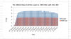
I'd like to work out why it's only measuring what it's measuring with the parallel resistors and values of all the components.
 
Top