Maker Pro
Maker Pro

Relacement for RIFA capacitor with 4 pins

awaisnasir98

May 21, 2024
9
Joined
May 21, 2024
Messages
9
Hi,

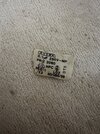
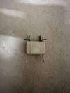
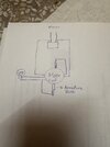
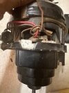
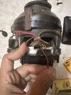
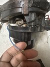
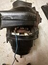
I have a old hoover vaccuum cleaner with a blown up RIFA capacitor with 4 pins. I’m looking for help to replace it with a newer version of the capacitor but a bit confused if i’ll need to install 2 instead of one or otherwise.

Marking states 0.1 uF 250V MP with type X2
 

Attachments

  • IMG_7607.jpeg
    IMG_7607.jpeg
    328 KB · Views: 8
  • IMG_7608.jpeg
    IMG_7608.jpeg
    348.9 KB · Views: 8

Bluejets

Oct 5, 2014
7,048
Joined
Oct 5, 2014
Messages
7,048
Two should be ok.
How was the original connected?
Circuit diagram would help.
X2 type is important as is the voltage.
 

awaisnasir98

May 21, 2024
9
Joined
May 21, 2024
Messages
9
The main terminal wires were connected on the pins highlight and from the other two, one side is going to motor and second one goes to a power bulb.

Im thinking like connecting one capacitor with one wire from main and other pin to the wire going for the motor. Then another capacitor in a similar fashion since i could only find newer capacitors with 2 pinouts
 

Attachments

  • 00c2e4ac-1fa0-4452-9891-09d7682df2ae.jpeg
    00c2e4ac-1fa0-4452-9891-09d7682df2ae.jpeg
    286.8 KB · Views: 6

Bluejets

Oct 5, 2014
7,048
Joined
Oct 5, 2014
Messages
7,048
So......what happened to the circuit diagram requested...???
Your "+ and -" doesn't make sense being an X2 cap (I'm assuming on mains AC)
No idea what the "bulb" is all about.
 

awaisnasir98

May 21, 2024
9
Joined
May 21, 2024
Messages
9
Couldn’t find it anywhere online for my specific model. It’s a vintage one but let me try again
 

awaisnasir98

May 21, 2024
9
Joined
May 21, 2024
Messages
9
This looks similar to what i have the wires going through
 

Attachments

  • IMG_7702.jpeg
    IMG_7702.jpeg
    186.2 KB · Views: 4

Bluejets

Oct 5, 2014
7,048
Joined
Oct 5, 2014
Messages
7,048
With the cap value shown . I'd say it is an RF interference cap and one could just chuck it and use the machine as is.
Your diagram shows a motor with 4 wire connections which appears wrong to me unless it is armature (x2) and field coils (x2).
No idea what the series bulb is for, my guess once again a circuit drawing error.
I would expect any lamp to be in parallel with the motor in an old Hoover machine.

RF suppressors mostly go across the mains input close to the motor with another cap to the frame BUT...........
Cannot be sure of the latter on your machine.
With things like this it is usually best to take a photo or two of the original BEFORE you attack it.
 

awaisnasir98

May 21, 2024
9
Joined
May 21, 2024
Messages
9
Sorry i mistook a brown wire for that of the bulb. Mains is actually going to the motor field coil first. I re-drew the diagram with additional pictures. Blue wire is from the mains on one side. The brown on the other side is the opposite mains wires connecting to the motor at the point where i have my finger
 

Attachments

  • IMG_7739.jpeg
    IMG_7739.jpeg
    172.5 KB · Views: 1
  • IMG_7738.jpeg
    IMG_7738.jpeg
    292.9 KB · Views: 1
  • IMG_7736.jpeg
    IMG_7736.jpeg
    275.5 KB · Views: 1
  • IMG_7734.jpeg
    IMG_7734.jpeg
    305.5 KB · Views: 1
  • IMG_7733.jpeg
    IMG_7733.jpeg
    382.4 KB · Views: 1
Top