Sir Pharaon . . . . .
I see that STAR is a newer manufactured Indian unit and NOT one of the STAR series of older Yamahaulers
It is looking akin to the Italianos early days Vespa scooters in styling . . . .with what looks like a VERY-VERY large comfortable seat!
Fortunate, that you are actually having an excess of generated power, instead of borderline or too low of generated voltage output !
PLUS I can see this incrementally faulting only at higher speeds, or additionally if you are not having, power consuming lights on.
If you find that the voltage is appreciably coming closer to normal with lights on you might consider using them in daylight driving, much the same as some cars do as an additional
" I SEE YOU " safety factor.
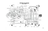
Consulting your wiring diagram . . . . . repeated at bottom page
HOW YOUR MAGNETO/GENERATOR WORKS . . . . .
Find the single
BLACK wire entry and we will work clockwise from it. That is system ground and shares a
commonality with 3 tandem windings and 1 single winding plus the units cast housing. Also, there is a

wire going housing to housing . . . . . . being common to ground.
You can then see the top 2 tandem winding set being in series and going to the left to exit as the
BLUE wire and the source of power to the units voltage regulator which routes outputted power to the right via the
ORANGE wire going to your battery.
Go back to the
MAGNETO/GENERATOR where the next tandem winding set, viewing clockwise, has one connection to the casting which would also be effectively connected to central ground wire . Its other connection exits as the
RED wire which is providing power for your
Capacitor Discharge Ignition module to run from.
The last coil is being a single trigger coil that will be outputting a voltage burst that is positionally related to your motors crankshaft position.
Here is a rundown of the last tandem coil set to
RED wire output and the positionally critical single trigger coil and its input into the
CDI unit.
You will initially be creating
Magneto/Generator spinning magnets rotary action on initial starter motor action operation from the storage battery. Then there is operational power coming down the
RED wire to the
Capacitor Discharge Ignition module, it is then using a built in DC converter to create an ~ 300 VDC voltage to charge a 1 ufd or so value of Poly/mylar film storage cap that . . . . at precise timings . . . .discharges into your High Tension Coil up at the top via the
BLUE wire running up to it. The High Tension Coils secondary then connects to the sparkling plug.
The critical timing is relevant to crankshaft positioning to the instant of the output pulse from that single winding which travels down the
GREEN wire to the
Capacitor Discharge Ignition module and an internal
Silicon
Controlled
Rectifier which then dumps that 300 VDC level of charged voltage, into the primary of the High Tension Coil.
The motor cranks, runs and rotates to repeat the process until shutdown.
Simultaneously the 2 series tandem windings are providing generated power to the voltage regulator module, which ascertains the degree of power transferal to the storage battery.
That is where you seem to have a bit excess at times and conditions.

The use of an additional shunt regulator would detect the rise in battery charge level above the norm and gently dissipate any overvoltage .
I would go for the 1st circuit and experiment with a 1K pot inserted so that you can set exactly what voltage threshold that you want any over voltage bleed off to occur.
At the Zener bottom lead /1k res / 4.7k res junction,they are to be disconnected and pot center rotor terminal goes to the now floating zener lead, one pot end terminal goes to the free 1k res and the pots other end terminal goes to the free 1k res. Then you set the pot to mid position and monitor voltage on higher revved up motor speed with lights off and trim in voltage to as high as you would ever want it to be. Then turn on lights and re check. A low threshold of 13.7VDC or upper of 14.2 would be benchmark levels to experiment with on your type of battery.
Considering that the lights will principally be using the stabilized, state of charge battery.
REPEAT of YOUR ALREADY HOSTED WIRING DIAGRAM . . . . . . . . . . . for quicker viewing access
 Thaaaaaaaaassssit.
73's de Edd . . . . . .
I wasn't originally going to get a brain transplant . . . . . but then, I changed my mind !
.