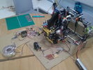
-
Categories
-
Platforms
-
Content
I now have a working channel!!! Mr kellys_eyeThere's 'bugger all' to the basic design of the filter section that couldn't be actually, physically constructed (on protoboard or hardwired) with sockets for the relevant resistor/capacitor values and you could play to your hearts content until you found something that worked.
How about building ONE channel that actually works?
It would be a damned sight quicker than a 700+ post regime and save some members time too.
It would also be nice for those who have taken the time and effort to assist in this thread to see something PRACTICAL from all their input. A few displays on some board doesn't cut it.
And if you haven't got a grasp of it by now then you need to reconsider your approach.
You're not getting away that easy... I'll leave a candle in the window for you; so you can find your way home.I'll post pics and I'll let you know when if I fix column 1!! thanks
not quite sure what that means but thanks anyway!!You're not getting away that easy... I'll leave a candle in the window for you; so you can find your way home.
It's a horrible thing to say.because as it was said before I dont want all the help annd comments made in this thread to have been a waste of members time
why would this happen? thanks
It's fine both the input power lines are working now!so about the power lines, as I said, when I hook in the power to one set of lines that are connected to the second set of lines (physically) it doesn't act as it should any ideas of why? makes no sense to me!!