Maker Pro
Maker Pro

Thrustmaster T300 main board USB Issue

Repairit

Aug 13, 2020
4
Joined
Aug 13, 2020
Messages
4
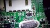
Hi looking at the main board on the T300 where the USB input comes in . I have 5v but then it seem to go into a filter .. I am not quite sure if this component puts 5v to the rest of the three pins . I have 5v pin 1,pin 2, 0v pin 3 1,5V pin 4 0V. (See pic) the main board is marked XF01 is it a fuse? anyone have a idea.. I am not getting 5V at the Opto, so the PSU won't switch on.. I have manually power the 5V at the Opto and all works fine ,,

thank you in anticipation. kind regards
Richard
 

Attachments

  • PICT0142.jpg
    PICT0142.jpg
    314.5 KB · Views: 175

73's de Edd

Aug 21, 2015
3,641
Joined
Aug 21, 2015
Messages
3,641
Sir Richard . . . . .

What it does seem there that you have yourself is a ferrite "dog bone" contrawound input inductor / line filter that has both of its fine magnet wire windings open, either :
  • 1 . . . Folded, spindled or mutilated
  • 2 . . . Burnt / or / blown open . . . . . ( burnt, being from a hot soldering iron dragged across by a pereson of either low intellect or intent of imparting damage upon.
The 5V would be indicative of the incoming input voltage and then encounterig the open winding and finding no circuit path over to pin 2 and into that via just to its left and then routing to the other side of the PCB..
Pin 4 is being connected to the ground plane that is GOING ALL OVER that side of the PCB with its multiple connections.
Pin 3 , with it having a VERY-VERY low Ω2 path to ground via the BLUE winding, therefore must NOW also be open with it reading a 1,5 V " sneak voltage " on it .

Find a replacement or rewind with two separate 40 + 40 turns windings of 38---42 gauge insulated magnet wire, as is being shown.

ILLUSTRATION . . .

upload_2020-8-14_5-4-51.png


73's de Edd . . . . .

Really fat people are really, really hard to kidnap !


.
 
Last edited:

Repairit

Aug 13, 2020
4
Joined
Aug 13, 2020
Messages
4
Woow topman .....thanks for the info 73's de Edd, I think it may have been damaged by the last owner of this thustmaster unit... can this ferrite "dog bone" be bypassed to get this board running..or will this cause problems ...I dont think i could rewind it... I can't seem to find any on the net and not sure what value i should be looking for.... thank you for the diagram,,,could i find any on a old laptop main board?


kind regards Richard
 

Repairit

Aug 13, 2020
4
Joined
Aug 13, 2020
Messages
4
Hi Bertus yes @73's de Edd did give me a suggestion ,, but i thought it would be easyer to rplace the part instead of trying to rewind one.. also in trying to get the old "dogbone" off is broke :( so thats why it would be better to replace.. the only thing that confuses me is that after the coil the connection goes to the SCLK pin which is connected to the ground pin 4 on the usb plug.. so why put 5v + back up that line? Surely this will blow the component... Is my understandind of this ,,, to give you more of what this is trying to achieve. all it dose is let the power supply know when the USB is connected to the computer or PlayStation so it can switch the power on for the thrustmaster racing wheel.. another fix i could do is run a 5v link to the opto , this would then switch the power on.. hopefully.. just as a note could i use two
EMIFILr (Inductor type) Chip Ferrite Bead one on each pad ?

kind regards. Richard :(
 

Repairit

Aug 13, 2020
4
Joined
Aug 13, 2020
Messages
4
Solution for the missing ferrite "dog bone" contrawound input inductor / line filter.. 73's de Edd picture is wrong..o_O the connection should be Pin 1 to Pin 3 & Pin 2 to Pin 4 .. if you connect it this way you will get +5V at the Opt \ Triac, if not you will blow the Opt\Triac by giving it -5v. I could not find another "dog bone" or do the rewind but I managed to use two "common Mode Choke Filter SMD Inductor WCM2012F2SF-900T04..:).it seem to do the job.. I have some spares if anyone need them:). The Thrustmaster T300 FFW is working fine now with no issues.. the only issue I have is getting my Lap time Down in ps4 F1 racing :(. thanks for all your input ….
 

Vastok

Feb 2, 2021
1
Joined
Feb 2, 2021
Messages
1
Solution for the missing ferrite "dog bone" contrawound input inductor / line filter.. 73's de Edd picture is wrong..o_O the connection should be Pin 1 to Pin 3 & Pin 2 to Pin 4 .. if you connect it this way you will get +5V at the Opt \ Triac, if not you will blow the Opt\Triac by giving it -5v. I could not find another "dog bone" or do the rewind but I managed to use two "common Mode Choke Filter SMD Inductor WCM2012F2SF-900T04..:).it seem to do the job.. I have some spares if anyone need them:). The Thrustmaster T300 FFW is working fine now with no issues.. the only issue I have is getting my Lap time Down in ps4 F1 racing :(. thanks for all your input ….

Hi @73's de Edd
What do you mean with "I managed to use two SMD inductors"?

Regards Vasyl
 

zee7ers

Apr 26, 2022
1
Joined
Apr 26, 2022
Messages
1
Hello dear my thrustmaster T300 moter is not working ichack the moter on supply it doesn't work tell me what to do
 

Seamass

Jun 7, 2023
1
Joined
Jun 7, 2023
Messages
1
Solution for the missing ferrite "dog bone" contrawound input inductor / line filter.. 73's de Edd picture is wrong..o_O the connection should be Pin 1 to Pin 3 & Pin 2 to Pin 4 .. if you connect it this way you will get +5V at the Opt \ Triac, if not you will blow the Opt\Triac by giving it -5v. I could not find another "dog bone" or do the rewind but I managed to use two "common Mode Choke Filter SMD Inductor WCM2012F2SF-900T04..:).it seem to do the job.. I have some spares if anyone need them:). The Thrustmaster T300 FFW is working fine now with no issues.. the only issue I have is getting my Lap time Down in ps4 F1 racing :(. thanks for all your input ….
Did you have any photos of what the end product looked like once you had soldered on the filters? I have a similar wheel. The TS-PC racer from thrustmaster. My friend pushed the USB out the back and broke the filter.
 
Top