Maker Pro
Maker Pro

Turn On and Off a Smaller Voltage from a Larger One

Madaxe

Aug 21, 2023
14
Joined
Aug 21, 2023
Messages
14
I have a circuit that is either at 0volts or 5volts, and I have a controller that has a 1.75volt signal that goes through a micro-switch. I want to delete the micro switch and use the 0V or 5V signal to control a MOSFET, Relay, Transistor or something

Can anybody help?

thanks

Marc
 

Bluejets

Oct 5, 2014
7,057
Joined
Oct 5, 2014
Messages
7,057
Show the circuit diagram.........
Signals can be many and varied.
 

TCSC47

Mar 7, 2016
148
Joined
Mar 7, 2016
Messages
148
Hi Madaxe
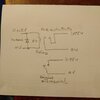
I'm not sure exactly what you want to do, but if I have it right, I would suggest just a simple mechanical relay as in the attached cct. diagram. I have had a look at your other post here and you say you don't have an electronics background, so I am not being condescending to suggest the most simple solution or attempting to teach how to suck eggs. The old KISS solution!

An example of such a relay
https://usa.banggood.com/5V-Low-Lev....2163&DCC=US&currency=USD&akmClientCountry=GB

This reference is through a UK website, so I don't know if it will work in the USA. Google "Bangood" and then look for "relay 5V" on the website. However there are plenty of other examples of relays on the internet.

The 1N4002 diode across the relay coli is to suppress inductive voltage spikes from the relay coil and is important if the 5V signal comes from a semiconductor of any sort, but is good practice in any case.

You need to check that the current that flows from the 1.75 V source can be coped with by the relay contacts.

Incidentally I think I saw a query from you about inverting the 5V signal? The relay could easily do this without any electronics by using the normally closed, NC, contacts rather than the normally open, NO, if it has them.

Hope this works for you.
 

Attachments

  • Electroni8cs point reply 2.jpg
    Electroni8cs point reply 2.jpg
    128.1 KB · Views: 6

Bluejets

Oct 5, 2014
7,057
Joined
Oct 5, 2014
Messages
7,057
Once again, show the circuit requirement.
Possible to couple together with opto isolator.
 

Madaxe

Aug 21, 2023
14
Joined
Aug 21, 2023
Messages
14
I give in i don't understand electronics, all i wanted was some basic help, and i appreciate some of the positive help i have received. I don't know how to draw a circuit diagram to be honest.

I have two separate circuits one at 5volts that gets turned on and off and one that has 1.75v that i want to turn on and off when the first circuit turns on and off.

So there is a direct relationship between the two circuits, i understand that i can put a relay between the two, i was looking for a smaller package solution

1702346025382.png
like a N-Channel MOSFET seemed to do what i wanted. When a voltage is applied to the Gate it allows current to flow from Source to drain or visa-versa. But i don't want to tie both grounds together and I think the voltages are additive is that correct?

1702347078791.png

I did find this as a IC equivalent to a relay,
1702347472269.png

Can anybody recommend one for my solution?

Thanks

Madaxe
 

danadak

Feb 19, 2021
797
Joined
Feb 19, 2021
Messages
797
The grounds, the negative side of both V supplies, are isolated ? If so then use a SSR
or optocoupler. What is the current flowing in the 1.75 supply ?

1702348745662.png


If not isolated grounds then a N channel MOSFET, drain connected to - side 1.75, source to
ground, gate to switched side of 5V. Use a logic level MOSFET, rated for current, low Rdson
(compute power to see if you need a heatsink on it).


Regards, Dana.
 
Last edited:

Madaxe

Aug 21, 2023
14
Joined
Aug 21, 2023
Messages
14
how do i measure the current? I know how to measure voltage.

Thanks
Madaxe
 

danadak

Feb 19, 2021
797
Joined
Feb 19, 2021
Messages
797
Do you have a digital multimeter ?

What is model of meter you have to do volts, ohms, current ?


Regards, Dana.
 

roughshawd

Jul 13, 2020
472
Joined
Jul 13, 2020
Messages
472
Ideal circuits are not proof of anything, so they will tell you to go ahead and experiment. There are usually components made that will do what you want or need, you just have to find them. There's a bit of a caveat with electronic circuits. There is never a promise, or a guarantee that anything will function the way it's supposed to. A smaller package is not always the most efficient or effective. Personally, I try to stick with functional, people don't seem to like dead electronics! When switching with power(v) use relays. When trying to switch current(a) use resistance, and ThePathOfLeastResistance. Or there will be arc. Or smoke. Or decomposition.
 
Top