I'm working on a pinball related electronics problem and I was wondering if you had any thoughts on it. I'm building Pinball mods and toys. I see a lot of requests to make this or that mod turn on and off with the GI. (General Illumination).
So I made a board that does that. You plug it into power, clip onto the GI somewhere, and you get 3 power outlets. One that's constantly on (passthough), one that turns on and off with the GI, and one that is dimmable that also turns on and off with the GI.
It works great and I want to make them available soon, but I really want to see if I can add one more feature. I'd love to make it work with matrix lights.
The light matrix is just like an LED matrix. There are 8 rows and 8 columns. Row 1 pulses with 6v, and column 1 opens a path to ground. This lights whatever lights is designated as 1.
The system continues, 1,1 ; 1,2 ; 1,3 ; 1,4; 1,5; 1,6; 1,7; 1,8; 2,1; 2,2 etc....
Here's what I've worked through to this point:
- At first I thought, "Easy, clip on to an insert. No problem. It's DC, the GI is AC. I have an inverter on the circuit and that will just pass the +6 and it will work the same. But it doesn't.
- Then I thought, no problem. Just pull the signal off the insert light and have it drive a 2n2222. There are two problems with this. First, putting the lamp on the base of a 2n2222 doesn't work because it get signal pulses from one leg or the other while the matrix is being cycled through. Also, connecting the "outbound" side of the light to the Base gives it a path to ground and it ends up lighting up the whole row or column.
- Then I though, OK, well, there are two sides of the matrix. I'll make an "AND" gate with two transistors. One that goes on when it gets +6v and the other when it's grounded. But I still had the "Path to ground on the base leg" problem.
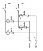
- So instead of regular transistors, I used mosfets. One N type on the "Pulse" side of the matrix, and a P type on the "ground" side of the matrix.
The last solution works - kind of. It's always flickering the load (an LED). Also, when the insert light is lit, (Allowing current to flow through the AND gate) it's still not really fully lighting my LED.
I already stretching my electronics knowledge here. I normally like to figure this stuff out myself, but I thought I would ask. I may have an incorrect impression of how the matrix works. Or my components might be too slow (or too fast, who knows) to sync up with the speed of the lighting matrix.
I connected my old O-scope ($60 on e-bay, an old analog scope from the 80's), to look at the pulses. They aren't square, and maybe that's why I get the flickering. So I thought maybe I can filter anything below a certain voltage to try and get a cleaner On/Off. But I'm not sure how to do that on a DC signal yet.
So I made a board that does that. You plug it into power, clip onto the GI somewhere, and you get 3 power outlets. One that's constantly on (passthough), one that turns on and off with the GI, and one that is dimmable that also turns on and off with the GI.
It works great and I want to make them available soon, but I really want to see if I can add one more feature. I'd love to make it work with matrix lights.
The light matrix is just like an LED matrix. There are 8 rows and 8 columns. Row 1 pulses with 6v, and column 1 opens a path to ground. This lights whatever lights is designated as 1.
The system continues, 1,1 ; 1,2 ; 1,3 ; 1,4; 1,5; 1,6; 1,7; 1,8; 2,1; 2,2 etc....
Here's what I've worked through to this point:
- At first I thought, "Easy, clip on to an insert. No problem. It's DC, the GI is AC. I have an inverter on the circuit and that will just pass the +6 and it will work the same. But it doesn't.
- Then I thought, no problem. Just pull the signal off the insert light and have it drive a 2n2222. There are two problems with this. First, putting the lamp on the base of a 2n2222 doesn't work because it get signal pulses from one leg or the other while the matrix is being cycled through. Also, connecting the "outbound" side of the light to the Base gives it a path to ground and it ends up lighting up the whole row or column.
- Then I though, OK, well, there are two sides of the matrix. I'll make an "AND" gate with two transistors. One that goes on when it gets +6v and the other when it's grounded. But I still had the "Path to ground on the base leg" problem.
- So instead of regular transistors, I used mosfets. One N type on the "Pulse" side of the matrix, and a P type on the "ground" side of the matrix.
The last solution works - kind of. It's always flickering the load (an LED). Also, when the insert light is lit, (Allowing current to flow through the AND gate) it's still not really fully lighting my LED.
I already stretching my electronics knowledge here. I normally like to figure this stuff out myself, but I thought I would ask. I may have an incorrect impression of how the matrix works. Or my components might be too slow (or too fast, who knows) to sync up with the speed of the lighting matrix.
I connected my old O-scope ($60 on e-bay, an old analog scope from the 80's), to look at the pulses. They aren't square, and maybe that's why I get the flickering. So I thought maybe I can filter anything below a certain voltage to try and get a cleaner On/Off. But I'm not sure how to do that on a DC signal yet.