Maker Pro
Maker Pro

Where to add a potentiometer to vary input voltage?

tkee

Oct 5, 2021
8
Joined
Oct 5, 2021
Messages
8
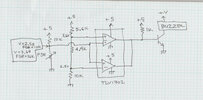
The voltage from the FSR varies between 2.5 V and 3.6 V as the FSR resistance varies from 10 k to 26 k. When the voltage is less than 2.5 V, the lower comparator holds the transistor base at ground; when the voltage is greater than 3.6 V, the upper comparator holds the transistor base at ground. In between these values, the 1 k resistor turns on the transistor, turning on the buzzer.
Circuit.jpg


Where can I add a pot to vary the 10K ohm/2.5v value that's input into the TLV1702? Thanks.
 

Bluejets

Oct 5, 2014
7,057
Joined
Oct 5, 2014
Messages
7,057
10k across 5v supply, centre to same input as the v_divider now.(remove existing)
You will need to establish the mechanical constraints to give you the limit to the range you require.
 

tkee

Oct 5, 2021
8
Joined
Oct 5, 2021
Messages
8
10k across 5v supply, centre to same input as the v_divider now.(remove existing)
You will need to establish the mechanical constraints to give you the limit to the range you require.

Thanks for the reply but wouldn't that vary both the upper and lower trigger points?

The circuit as it is keeps the buzzer off until the FSR reaches 26K ohms (light force), then turns it on until it reaches 10K ohms (heavy force) then turns it off again. I would like to be able to adjust the point at which it turns off at the heavy force point. youtube.com/shorts/MElcl9LruXY
 

danadak

Feb 19, 2021
797
Joined
Feb 19, 2021
Messages
797
Answer here :


Bluejets

Oct 5, 2014
7,057
Joined
Oct 5, 2014
Messages
7,057
The circuit as it is keeps the buzzer off until the FSR reaches 26K ohm
That might be as it is now but the resistance is really unimportant....the voltage from the divider is.
 

Bluejets

Oct 5, 2014
7,057
Joined
Oct 5, 2014
Messages
7,057
Where can I add a pot to vary the 10K ohm/2.5v value that's input into the TLV1702?
Your words, not mine.
If your need is to change the complete circuit to suit different thresholds, you should simply say so, rather than offer your version of a fix in your query.
 

tkee

Oct 5, 2021
8
Joined
Oct 5, 2021
Messages
8
Your words, not mine.
If your need is to change the complete circuit to suit different thresholds, you should simply say so, rather than offer your version of a fix in your query.

My knowledge is obviously limited but how else are you going to vary "...the voltage from the divider..." as you suggested in an analogue circuit without a potentiometer?

I do not need "to change the complete circuit to suit different thresholds" again as you state, just "vary the 10K ohm/2.5v value that's input into the TLV1702" as stated in my OP.
 

Bluejets

Oct 5, 2014
7,057
Joined
Oct 5, 2014
Messages
7,057
So, redesign the comparitors to suit your needs.
You have 2 voltage dividers, change whatever to achieve what you want....simple ohms law.
 

tkee

Oct 5, 2021
8
Joined
Oct 5, 2021
Messages
8
So, redesign the comparitors to suit your needs.
You have 2 voltage dividers, change whatever to achieve what you want....simple ohms law.

If I knew how to do that why would I come here and ask?

I see from your reply history and 6000+ post count you like to sit behind your keyboard and belittle others rather than actually offering a solution, sounds to me like you really don't know what your talking about or simply have a reading/comprehension issue.

No problem, I got answers on other forums from good folks that were actually able to understand my question right away and offer a solution rather that posting nonsense, maybe you could learn something from them!
 
Last edited:

Bluejets

Oct 5, 2014
7,057
Joined
Oct 5, 2014
Messages
7,057
you really don't know what your talking about
Oh snowflake, how would one who has no idea come to that conclusion?
You'll search my history but won't get off your butt and do some searching on the tips already given. Good luck with your future.
To allay any doubts, I do know what I'm talking about, thankyou.
You've been told the answer, what more do you want.
No way I'm about to draw it up for you, work it out yourself.......learn by doing.
 

tkee

Oct 5, 2021
8
Joined
Oct 5, 2021
Messages
8
If you did know what you were talking about you'd have answered my question correctly the first time, instead when you are nicely told you are wrong you start calling people names and trying to belittle them. You must be the resident troll around here.

Never argue with an idiot, they will only drag you down to their level and beat you with experience. Mark Twain

PLONK!
 
Last edited:

Delta Prime

Jul 29, 2020
2,137
Joined
Jul 29, 2020
Messages
2,137
Never argue with an idiot, they will only drag you down to their level and beat you with experience. Mark Twain
Man... in all my years...I never come across that quote from Mark Twain.
Thank you sir for the information.

photo_1697131554892.png
 

air_gap

Oct 21, 2023
8
Joined
Oct 21, 2023
Messages
8
Never argue with an idiot, they will only drag you down to their level and beat you with experience. Mark Twain


Man... in all my years...I never come across that quote from Mark Twain.
Thank you sir for the information.

You misquoted him. The real quote is:

"Never wrestle with a pig. You just get dirty and the pig likes it."
-Mark Twain

The concept is, of course, metaphorically similar however.

OT: Consider a Shmidt Trigger. It performs a nearly identical function to the circuit in your OP, uses only one op-amp (comarator) instead of two and requires fewer passive components. I didn't run the numbers on your circuit but a Shmidt is probably (way) more stable also.

Link:


tkee

Oct 5, 2021
8
Joined
Oct 5, 2021
Messages
8
You misquoted him. The real quote is:

"Never wrestle with a pig. You just get dirty and the pig likes it."
-Mark Twain

That's another of his famous quotes, both of which could be aptly applied in this circumstance.


air_gap

Oct 21, 2023
8
Joined
Oct 21, 2023
Messages
8
There are also better ways of designing the voltage reference leg with the 5.6K, 4.4K and 10K resistors in it that are MUCH less dependent on the supply voltage.

Hint: (zener) diodes.
 

tkee

Oct 5, 2021
8
Joined
Oct 5, 2021
Messages
8
Thanks, I'm using a regulator and so far it seems to be holding steady. I plan to use 3 x 1225 coin cells to power it so input voltage shud be around 9v.
 

Delta Prime

Jul 29, 2020
2,137
Joined
Jul 29, 2020
Messages
2,137
Thanks to everyone for these fine examples.
I was planning on doing the same.
To thread starter; forgive me for barging in, this is your thread alone.
I simply had to express my gratitude for the two explanations and schematics thanks again.
"We are not here to see through one another but to see one another through."
-Anne Lamott

I'm a southpaw!
photo_1698099005801.png
 
Last edited:
Top