Maker Pro
Maker Pro

Wiring diagram of 18650, HX-3S-01, XW228DKFR4 and a LED strip

joz

Apr 7, 2024
6
Joined
Apr 7, 2024
Messages
6
Hi!
If somebody would be willing to have a look at the drawing I made, and to let me know please if everything would be working properly? Thank so much!
diagram.png
 

Delta Prime

Jul 29, 2020
1,987
Joined
Jul 29, 2020
Messages
1,987
I have never seen this type of drawing before...very creative.
Welcome to Maker Pro. :)
Are you building a battery backup?
Where is the power source?
The batteries themselves?
And will that switch be open or closed when your charging your(3S)Three series battery pack?
 
Last edited:

joz

Apr 7, 2024
6
Joined
Apr 7, 2024
Messages
6
Thank you!
This is a LED strip powered by 3 pieces of 18650 rechargeable batteries. So on this drawing we have all the elements for that, except that I maybe forgot to mark the power adapter source Voltage. It's 12.6V, 2A, DC.
I don't know if the drawing is creative but that's how I made it :) I'm not professional, obviously.
Regarding the switch, it should be open while the batteries are charging. I am actually not sure, what would happen if the switch is closed while charging and if that would affect the charging process or not.
 
Last edited by a moderator:

joz

Apr 7, 2024
6
Joined
Apr 7, 2024
Messages
6
Version 2diagram-v2.JPG
 
Last edited by a moderator:

joz

Apr 7, 2024
6
Joined
Apr 7, 2024
Messages
6
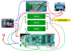
I tested this and it all works fine except one thing: batteries won't charge. Also, there was one black wire soldered to P- when I first time opened the casing of this device. I never figured out where was that connected but it must be the reason why the batteries won't charge.
Here is the image:
diagram-v7.png


Any idea where should I solder that end of the wire please?
 

Bluejets

Oct 5, 2014
6,942
Joined
Oct 5, 2014
Messages
6,942
Charge socket does not look correct but difficult to say as image does not show the connections properly.
Do you have a link to the parts details?
Looks like you have 2 (red) positive leads on either side of the panel socket internal switch and if they are not the correct orientation, your unit will not charge.

What is the module top of frame?
 
Last edited:

joz

Apr 7, 2024
6
Joined
Apr 7, 2024
Messages
6
Charge socket does not look correct but difficult to say as image does not show the connections properly.
Do you have a link to the parts details?
Looks like you have 2 (red) positive leads on either side of the panel socket internal switch and if they are not the correct orientation, your unit will not charge.

What is the module top of frame?
Thank you for answer.

The thing is that before I removed the old batteries, the device was turning on the lights while the charger is plugged in. Now, after replacing the batteries, lights are working even without charger plugged in. The only problem is that the batteries are not charging. I tried few different BMS 3S 10A boards so far. I will insert the image at the end of the message. First one, on top, was inside the device before I replaced the batteries. Once I replaced the batteries, I didn't get any output voltage on P+ and P-. So I thought the board is dead. I replaced it with the one in the middle, on the photo. It was the same, output is 0V. Then I learned the board needs to be activated. After activation I got the output of 11.02V, as it is now. But no charging. So I tried the third board, this is on the bottom of the photo. And that one is in use right now. But no difference: No charging and the voltage is 11.02V on P+ and P-, even if I plug in the charger.

Yesterday, I tried to short connect those 2 negative wires from charger connector. Nothing changed.

The other "red" lead which you see on panel socket is actually black. Traces of red color remained after separating the lead from the red one.

I don't have a link to part details, unfortunately. Batteries are EVE ICR18650/26V 2.55Ah around 7.5A, refurbished. Charger is Li-Ion 12.6V 2A. Boards are BMS 3S 10A. The indicator on the top of my diagram is showing the current batteries capacity. Model is on the photo: XW228DKFR4.
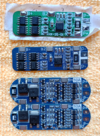
BMS 3S 10A boards_scaled_down.png
 

joz

Apr 7, 2024
6
Joined
Apr 7, 2024
Messages
6
Got everything working now properly. The first diagram was wrong. Here is the correct one:

WORKING_DIAGRAM_THIS_Screenshot_20240417_144527.png
 
Top