Learn how you can easily create a music machine with littleBits modules and Blockly coding.
In my two previous articles, I introduced the littleBits electronics modules created by Ayah Bdeir and showed you how to build a remote audio oscillator.
In those two articles, the littleBits electronics module construction was presented along with enhancement techniques for adding an external speaker to the infrared (IR) operated audio oscillator. The Proto Bit introduced in the oscillator project allows such enhancements to occur your own circuits to work directly with the littleBits electronic modules.
In this article, I will show you how to build a simple music machine using littleBits modules, including a codeBit, speaker Bit, power Bit, Proto Bit, and a push button Bit.
We will cover the blocky codes for playing musical tunes (in this case Mary Had a Little Lamb) and for observing the music waveform produced using a mini oscilloscope. These codes will also be available at the end of the article.
Required Components
The simple music machine needs five basic littleBits electronic modules:
- power Bit
- push-button Bit
- codeBit
- Proto Bit
- speaker Bit
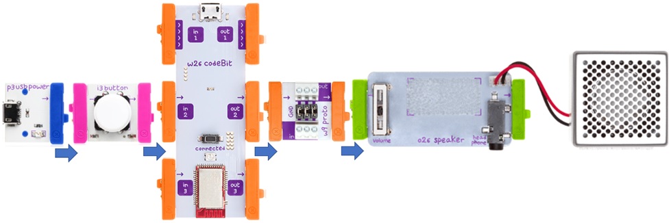
Figure 1. The littleBits required for building the Simple Music Machine.
The bits will snap together in a single line allowing the construction of the musical device.
A 9V battery is also required to power your device.
Building the Simple Music Machine
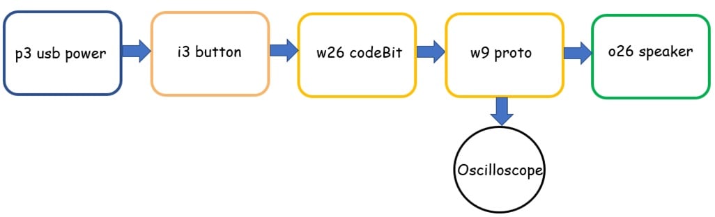
To build the simple music machine you must secure the littleBits electronic modules shown in Figure 1 in proper order. The block diagram in Figure 2 shows the correct order for the littleBits modules.
Figure 2. The Simple Music Machine Block Diagram.
Following the correct order for snapping the littleBits together is very important, because it shows the musical device's waveform signal using an oscilloscope. The oscilloscope will attach to the Proto Bit allowing us to see the waveform signals produced by the codeBit tones.
Figure 3 shows where you will attach an oscilloscope in the Proto Bit to view the codeBit music tones’ waveform signal. An analog DC voltmeter can also be attached to the Proto Bit to create a volume unit (VU) meter or metronome effect for the musical device.
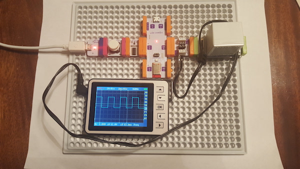
Figure 3. The output waveform produced by the simple music machine can be observed with an oscilloscope.
To ensure proper electrical connectivity is established between the bits, slightly press the electronic modules together when they snap into place. You can test the simple music machine’s electrical connections by powering the device with a 9V battery. Slide the power Bit’s small slide switch to the ON position, and the red LEDs on the power Bit and codeBit will light up.
Figure 4. The proper placement and attachment for building the simple music machine.
With both LEDs on, your device is ready for programming. Here’s the completed music machine I built including a mini oscilloscope attached to the Proto Bit.
I included a latch bit to allow the music to continually play from the device.
Figure 5. My fully functional simple music machine.
codeBit Fundamentals
The heart of the simple music machine is the codeBit.
The codeBit is a small programmable circuit that allows you to create a variety of devices including robots, electronic games, toys, and even smartphone operated radios.
If you are an educator, the codeBit is a great instructional tool for integrating technology into your classroom. With the codeBit, you can introduce coding concepts and electronics into your classroom with STEM and STEAM curriculum.
If you flip the codeBit over, you can see a small black square microchip along with other tiny electronic parts mounted on the printed circuit board (PCB). The microchip is an ATSAMD21 32-bit microcontroller (Figure 6). The microcontroller allows for adding programming code features and functions to the codeBit.
Figure 6. The ATSAMD21 microcontroller can be found on the bottom side of the codeBit's PCB.
The layout of the ATSAMD21 microcontroller on the codeBit’s PCB is based on an input/output (I/O) design scheme of 3 and 3. There are 3 inputs and outputs connectors. One of the output connectors (out 1) is designated for driving a littleBits LED matrix.
If you are not using the LED matrix, then out 1 can be used for driving other littleBits electronic modules like a bar graph, motors (servo and DC), and LED displays. Figure 7 shows the arrangement of the littleBits codeBit I/O connectors.
Figure 7. The electrical functions for the codeBit's I/O connectors.
The Blockly Code
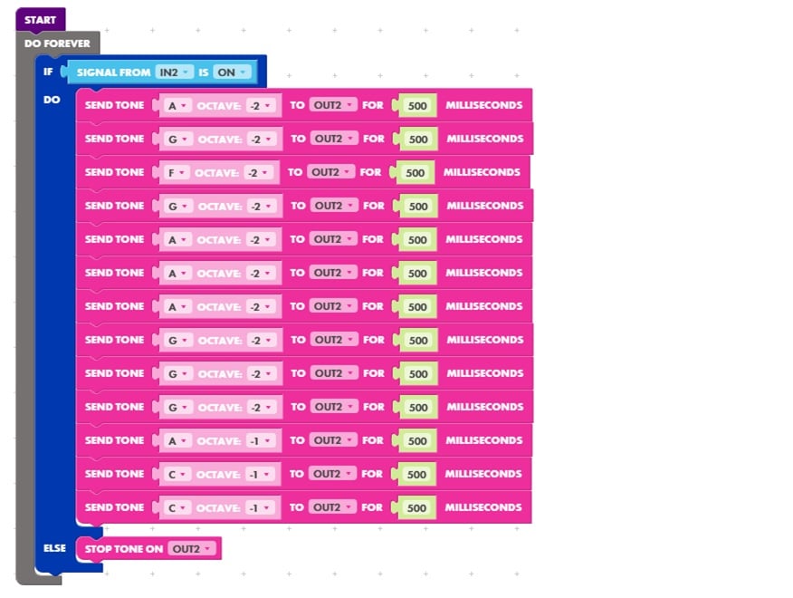
The code used to play Mary Had A Little Lamb was built using Blockly code.
Blockly code is a software development product developed by Google to allow novice Makers unfamiliar with coding to create programmable devices. The programming instructions are embedded in colorful blocks. These blocks instruct the codeBit to perform dedicated tasks.
As you play with the Blockly blocks from the menu on the right-hand side, the equivalent programming language code will be displayed. Selecting the down arrow will show the equivalent code in several programming languages, including Javascript, Python, PHP, Lua, and Dart.
With this mini Blockly code training session, you will have the skills and knowledge to understand and modify the codeBits Blockly code shown in Figure 9.
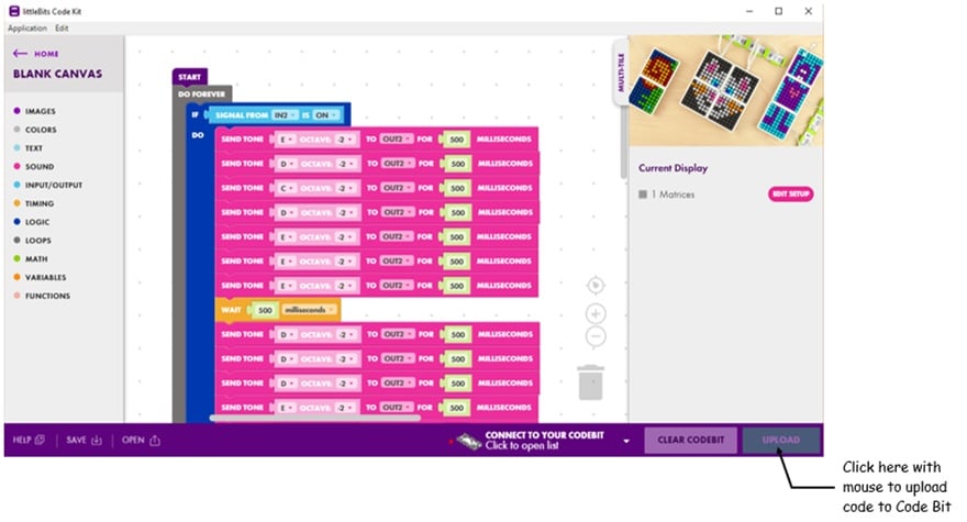
Figure 9. The Blockly code for playing Mary Had a Little Lamb on your simple music machine.
Programming the codeBit
To program the codeBit, connect a USB cable between the codeBit and your laptop computer or desktop PC.
The codeBit software is a free download and can be obtained from the littleBit’s download page.
Figure 10. The codeBit software is available as a free download from the littleBits website.
Once you install the software and attach the codeBit to your laptop computer or desktop PC, you are ready to code the musical tune shown in Figure 9. To upload the code, click the Upload button in the lower right-hand corner of the window (Figure 11).
Figure 11. Click the Upload button to program your codeBit.
When the codeBit begins receiving the program, a small green LED on the Bit starts to flash.
After uploading the program to the codeBit , adjust the volume on the speaker bit and press the push-button Bit. You will hear the musical tune playing through the speaker Bit. Congratulations on building your simple music machine!
With each press of the push-button Bit, you will hear the tune through the speaker and see a square wave visible on the attached oscilloscope. The frequency measured is around 165 Hz. Explore the code by changing the notes and observing the change in frequency.
Figure 12. The oscilloscope measures a frequency of 165Hz from the musical tune Mary Had a Little Lamb.
To take this project further, you can purchase different input bits to create unique human interaction controls with the simple sound machine. In a future article, I’ll show you how to add your own electronic circuits to a littleBits device using the Proto Bit.