Make this quick, simple robot that can operate in as large of a range as your network provider's coverage area.
Hello World! In this post I will be showing you how to make a cellphone controlled robot. Controlling a robot using a cellphone is not as complicated as you might think. It is a very simple project that you can make with a few components and in very little time. This robot has the advantage of range as the controlling range of the mobile controlled robot is as large as the coverage area of the network provider.
This project can be made in two methods:
- Without using micro controllers (hence no coding is required)
- Using Micro controllers (Atmega/ Arduino) which requires coding
In this post, I will be making the mobile controlled robot using the 1st method (without Micro controllers).
How Does the Mobile Phone-Controlled Robot Work?
The robot is controlled by a cellphone that makes a call to a second cellphone that is attached to the bot. When any key is pressed on the controlling phone, while the phones are connected on call, a tone corresponding to the key is heard at the receiving end of the call. This tone is called a
Dual Tone Multi Frequency (DTMF). When the mobile robot receives this DTMF tone through the phone, the tone is accepted through the DTMF decoder MT8870 IC. This IC decodes the DTMF tone to its equivalent binary digit and this binary number is sent to the motor driver
L293D. The decision for movement of the mobile robot is then taken by the Motor Driver. This controls the geared motors accordingly to provide forward, backward, left or right motions. You can use the table for understanding the controls of the robot.
Step 1: Connecting the Circuit for the Mobile Controlled Robot
Make the circuit as per the given schematics. The circuit is divided into 4 parts:
- Power supply
- CM8870 DTMF Decoder IC connection
- L293D Motor Driver IC connection
- 3.5mm Jack Connection
Power Supply
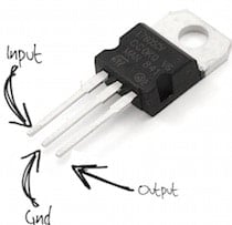
I have used a 12V geared motor for my robot here, so I needed a 12 power supply for it. But the two ICs in the circuit can handle only 5V supply. So, to regulate the voltage I have used a 7805IC. It takes the input voltage of 12V and gives a regulated output of 5V for the IC. For making these connections:
- Solder the IC7805 (Voltage Regulator) to the perfboard and place a 10 µF capacitor with its legs at the INPUT & GND pins of IC 7805. Place another 10µF capacitor between the GND & OUTPUT of IC7805.
- Take the positive supply from the battery and connect it to INPUT of IC 7805. Also connect its negative supply to GND.
- You will receive 5V supply at the output pin. To verify the power flow, connect an LED to the output pin via a 1K resistor.
CM8870 DTMF Decoder IC Circuit
- Solder the DTMF Decoder IC on the perfboard & connect the legs of 3.57Mhz crystal to Pin 7 and 8.
- Solder a 100K resistor from Pin 3 to Pin 2. Connect one end of another 100K resistor to Pin 3 and the other end to a 0.1µf ceramic capacitor. Leave the connection of other end of the ceramic capacitor free. I will discuss it in a later step (3.5mm Audio Jack Connection).
- Solder a 0.1uf ceramic capacitor between Pins 17 and 18
- Solder a 330K resistor to Pin 17 from Pin 16
- Join Pin 1 and Pin 4 together.
- Join Pin 5, Pin 6 and Pin 9 together and connect it to GND.
- Join Pin 10 and Pin 18 together and connect it to OUTPUT pin of IC7805 (5v)
- Pins 11, 12, 13, 14 are the output pins of the DTMF Decoder which are to be connected to the Pins 15, 10, 7, 2 of the Motor driver IC L293D, respectively.
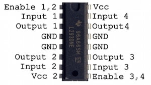
L293D Motor Driver IC Connection
- Provide 5v supply to Pins 1, 9 and 16 of L293D.
- Pin 8 is given the voltage(12V) for the Motors, so it is connected to INPUT of IC7805.
- Pins 4, 5, 12 and 13 are to connected to GND.
- Connect terminals of one motor to Pins 3 and 6 (Output 1) and terminals of the other motor to Pins 11 and 14.
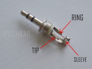
3.5mm Jack Connection
There are three different layers for the 3.5mm audio jack. These are the Tip, Ring and Sleeve. The tip and ring are connected to the GND. In the DTMF Decoder IC circuit section, we had left the connection of a 0.1µf ceramic capacitor which is to be connected to the sleeve. You can check the pictures given below for further clarification.
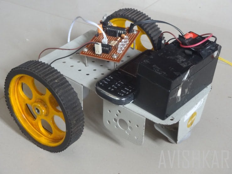
Step 2: Assembling Circuit and Parts on the Chassis
After completing the circuit on the perfboard, connect the 3.5mm audio jack to the mobile phone placed on the mobile robot. Turn on the auto answer mode in the call settings of the receiver phone. Enable keypad tones in the cell phone that will be used for making the call. Switch on the 12V power supply to the circuit. Now the robot is ready to be controlled through your mobile phone. Make a call to the receiver mobile on the robot and use the above table for the controls of the robot. Check out the working of the cellphone operated robot here in this video: