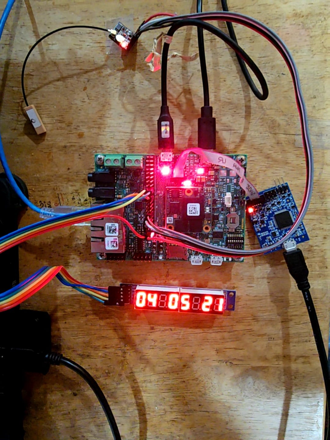
This article evaluates the creation of building a stratum 1 precision edge clock based on using the PHYTEC RT1170 dev board, which is based on the NXP RT1176 chip. This includes: a description of the additional required hardware, an expanded code listing, and a comparison of the software baseline (code included) with a hardware implementation.
Overview and System Architecture
This project details using a PHYTEC RT1170 development board to build a working Grandmaster Clock. The Grandmaster clock, which provides precision PTP and NTP timing, is a core component to any device with common connectivity but diverse locations: Data Centers, Telecommunications, IoT devices, Power Grids, Factory Systems, and Secure Computing.
This article will focus first on the design philosophy, followed by a discussion of connecting the additional hardware. Then the Software based Time Server Implementation is explained (and included as downloadable assets for learning and experimenting) and followed by a comparison with Hardware based Time Server Implementation as a case study in the improvements that can be made if hardware is utilized.
Design Philosophy
The NXP RT1176 chip contains ARM two cores, a Cortex M7 (CM7) and a Cortex M4 (CM4). All code for each core lives in different, segmented parts of memory that can be linked to different peripherals using the device tree. Since security was a key factor in the design of this system. To that end, one of the key components of the design was to decouple the network facing layer (the CM7 core) from the timing layer (the CM4 core). This was achieved by focusing on the CM7 core for the network and configuration side of the device. Included in the CM7 code are the PTP and NTP software stacks, the networking stack, and the user interface on the serial (a basic CLI). Doing this left the CM4 to focus solely on the timing functions without fear of interference from the CM7 core (more on this in the following section). The CM4 handles all of the GPS messages and the timing loop discipline of the device.
To refrain from having to write everything from scratch, both the CM7 and CM4 utilize sysbuild to support Zephyr OS. This makes things such as logging, terminal integration, and even supporting items like a display a simpler at least in theory...
Inter-Core Communication (IPC)
The other core reason for choosing to use Zephyr is that it supports OpenAMP for IPC communication between the cores. In practice this allows for the timing system to push data to the CM7 core but never to take in data from it. This means that even if the networking stack has an exploitable vulnerability, it will not be able to poison the time coming from the CM4 (which has no user or network facing code). Also, based on the design, even if the time is changed by the user on the CM7, the next IPC message will overwrite it back to the correct UTC time.
One issue that surfaced was that the OpenAMP example code for Zephyr did not enter until Zephyr OS 4.4.0 (so we can assume it was not supported until then) and the PHYTEC documentation at the time of writing is intended for version 4.1 and 0.17 of the SDK. Therefore, in order to support the newer version, I needed to pull the 1.x version of the SDK and the Zephyr 4.4.0 application tree. This only left a "small" issue, that between these versions, support for the CM4 core is completely dropped in the PHYTEC 4.4 tree. This required substantial work to port the dedicated NXP version of the CM4 core and update it for the PHYTEC atlas board config. As a result, it might be very hard to build the code that is attached (see the last section of this article for the details of what is included). I did not realize that porting the entire environment in a way that is not currently supported by PHYTEC would be required when I started the project. Therefore, I did not fully document the process so unfortunately I cannot easily share the steps required to setup your build environment correctly. The entire build directory is around 2 GB so it would be hard to readily provide that for distribution. Instead, a precompiled elf file is provided that can be flashed to the board for casual testing.
External Hardware Description and Wiring
Before continuing on how the code itself works, it is worth taking a moment to address the additional hardware that is needed to make this work.
The kit from PHYTEC was incredibly well thought out, including many items for connecting and flashing the system (JTAG), various cables and connectors, a solid power supply, and a quick start guide. But there were a couple of things, naturally, that are needed specifically for this project.
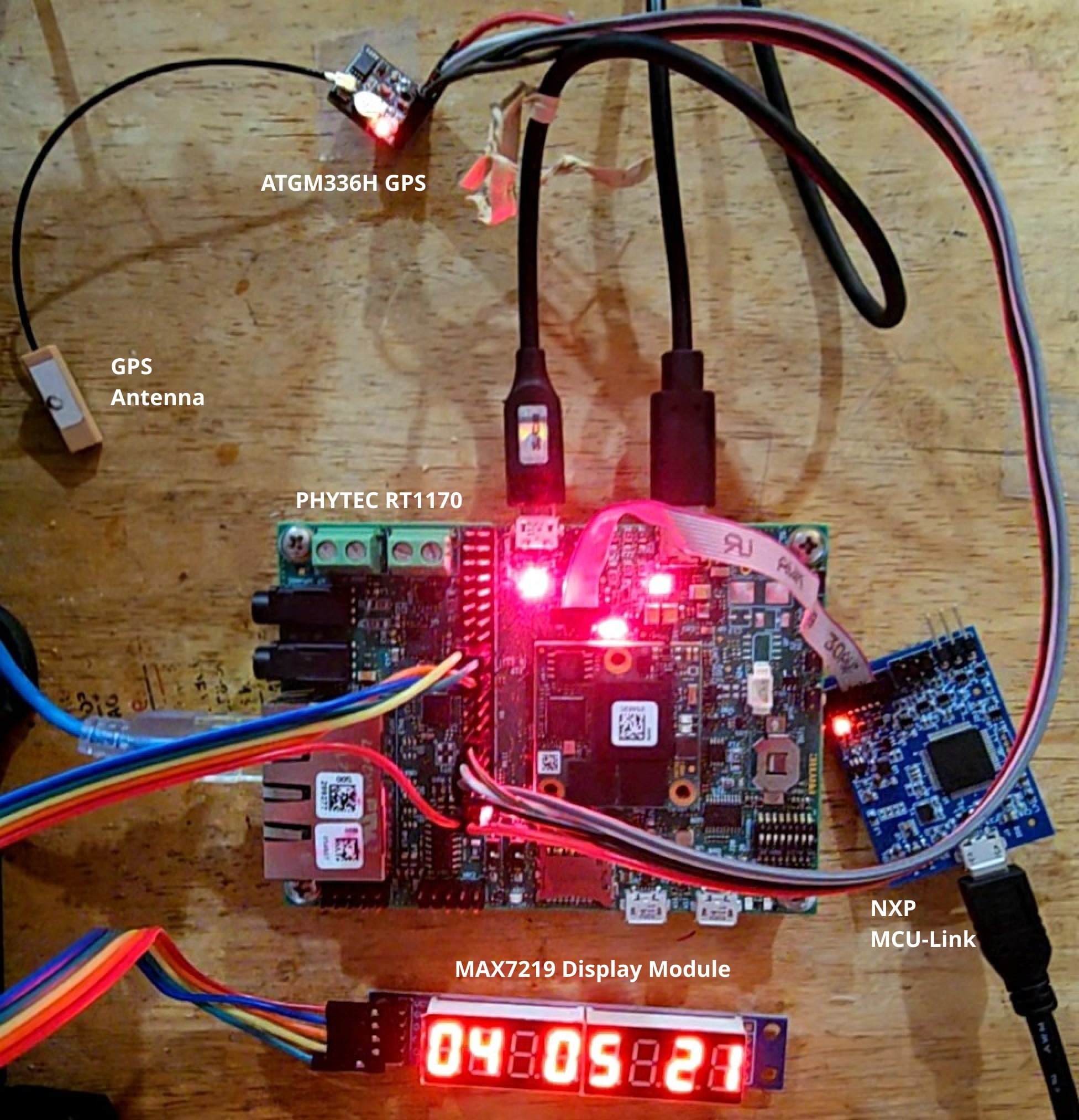
- A GPS Module. I chose an ATGM336H as it was the cheapest GPS module that had both GPS info via UART and Part Per Second (PPS) pins. Assuming you have standard NMEA GP*** and BD*** verbs, the source code likely will work with what you have. Another nice thing about this module is that it has an LED that lights solid when looking for link and blinks at 1Hz when there is link. So some visual debugging built right in.
- An 8 Digit 7-segment display based on the MAX7219. Optional, but very cool. This is used to display the current time in UTC and acts as a good check for connected devices or analog watches.
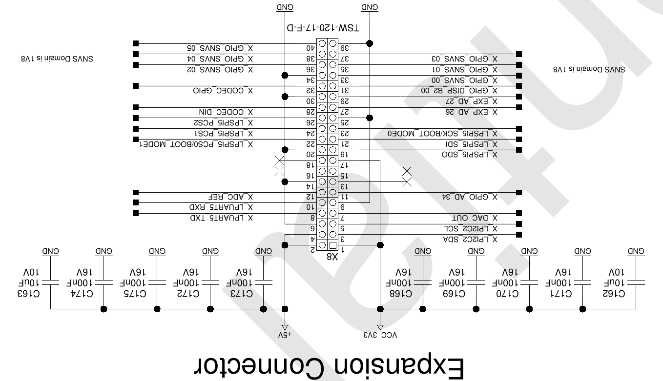
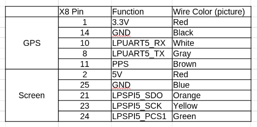
However, wiring them up was very confusing. This was, in part, due to the fact that no pinout document was provided by PHYTEC for the pins, so the only option was to dive into their NextCloud and read the schematics. And, this is where the second problem came in; there is no marking on the board, at least that I saw, to say which pin is pin 1. Since all of their pictures and marketing information, and even schematic, all had pin 1 in the upper left hand corner of the board (by the audio outs), that is what I went with too. This was not the case, and instead it turns out to be 180 degrees different (see photo below). Needless to say, it is a good thing that I purchased more than one screen and started with that first. Also below, in Table 1, is a listing of the connections between the modules and the PHYTEC RT1170 board.
Image 1: Correct pin out referenced to the upper left hand corner of the board.
Table 1: Connection Pinouts
Software Reference Implementation
With the hardware connections out of the way, and the initial comment about the porting in the IPC completed, we can talk about the Software Reference Implementation. Just as a quick reminder, the LPUART1 is the CM7 core and the LPUART6 is the CM4 core output. Both output for their respective tasks.
For the most part I will refrain from going through each part of the code line by line, there are ample comments in the code and you are welcome to dive into it to examine the process. My goal is to explain what each file handles to give you a roadmap for how to interact with the code and better understand what it does. I have split this into two parts, one for the CM7 core and one for the CM4 core. Also note that there are many printk's throughout that provide timing information and debugging and they were left in for better learning of what is running "under the hood." Feel free to comment them out for an instant performance boost.
CM7 Core
- main.c - Handles all of the OpenAMP communication (as it was already in place from when I got the working example completed) as well as calling and spawning several threads for the edge clock. There is also a simple "dummy" variable set and get function at the top of the code that I was using when first testing Zephyr OS. It may be really helpful to look at first if trying to develop a simple function for the OS (the value is stored in memory, so any reset or reboot will cause it to be lost).
- display.c - This handles all of the MAX7219 code. There is admittedly some bit bashing in here, as well as some defines at the beginning to support changing the layout of the time (you are welcome to change the screen output to your liking).
- gnss_clock_disc.c - Has several defined thresholds for the GNSS system for how you deal with the initial sync and the occasional lost sync packet. Once the clock is disciplined, it steps the internal clock to the correct time and continues to hard step the clock if it drifts too much.
- gnss_disciplined_clock.c - Contains several PID tunables for how quickly your clock converges and deals with PPS messages. Unlike gnss_clock_apply()/CLOCK_REALTIME (see gnss_clock_disc.c), this NEVER steps except on a genuinely large error or first sync: between updates it is a pure linear function of Zephyr's monotonic uptime (k_uptime_get()), and each ~1 Hz update only nudges phase and frequency by a small damped amount. External PTP clients therefore see continuous, smoothly advancing time instead of a step every second (in theory, due to software execution time there may still be some choppiness).
- net.c - First and foremost establishes the IP addresses for the system on both ETH0 and ETH1, although at the time of software implementation 1G ENET was not working (so stick with ETH1) for changing the settings of the IP, Gateway, and Netmask. These are hardcoded into the software implementation of the system so if you want different addresses you will need to change them here. Otherwise, the code is pretty standard for bringing up the sockets. The system can be pinged and can ping back if needed. Also, the NET_SHELL is enabled so other commands under net can be used for debugging.
- ntp.c - Provides a custom NTP server for providing 48-byte fixed length non-authenticated timing data derived from the system clock, that is in turn disciplined by the CM4 core. If for some reason you need to change the NTP port to be non-standard, it would be done from this file.
- ptp.c - The is the core of the custom PTP server implementation and has defines to set the ports and the multicast address in case those need to be changed. There is also TAI offset seconds hard coded in as well (see final section for more details) and there is a comment for where to find if the leap seconds change in the future. Beyond that, this is the heart and sole of the PTP implementation. Due to being a software implementation, it utilizes a "two step" connection, where the device records the exact transmission timestamp of an initial sync message and then sends a separate follow-up message to deliver that recorded time to receiving clocks.
CM4 Core
- main.c - Much like the CM7, handles the IPC code and launching of various threads and tests.
- gnss_ipc.c - Provides connective tissue between GNSS timing data and the RPC queue. Generates and sends the timing messages to the CM7 core
- nmea_parser.c - Provides a library of functions to deal with the timing information and possible differences in format. Can parse RMC and ZDA tags, as well as multiple possible time formats.
- gps_uart.c - Contains UART bus related files. Provides the setup for LPUART5 and the parsing of the UART lines from the GPS module. This is by far and away the "chattiest" file, as it prints both the nmea breakdown and the raw GPS UART messages so if you like your sanity, you may want comment out one or both of these printk's unless you are debugging any issues.
- pps_capture.c - Manages all of the information related the Part Per Second (PPS) interrupt that is fired by the PPS pin from the GPS module. This includes starting up threads, managing timing updates, and how to deal with missed pulses for when the interrupt was late or did not arrive. There are a couple of tunables here if you want to be more precise or hold on longer without a PPS pulse.
- time_sync.c - Pairs the most recent GPS PPS edge (hardware cycle count, from pps_capture) with the next decoded, fix-valid RMC sentence's UTC date/time (from nmea_parser) to establish an epoch-seconds to cycle-count reference.
Of course, if you are an engineer all of this is neat but what you want to see are the results. I know I do. To save on describing them twice, I will introduce them in detail for comparison in the case study. And speaking of the Hardware Case Study...
Case Study: Software vs. Hardware Results
Currently, the hardware based timer design is in full gear. While it is still in a testing and development phase, I did want to go ahead and provide some preliminary results from it, to contrast with the software results and show, in real terms, how utilizing the hardware registers can greatly improve the design.
To begin with, impressive stability can be gained by utilizing the hardware registers. In my initial, non-service measurements, the internal phase lock could be within ± 3 ppb. Even with the load of the system and serving PTP, its max drift was ± 10ppb. The software version of NTP, by comparison, can have steps that are easily ± 100ms. The timing improvement also comes from forcing the system to run off a slower but more stable crystal based clock as opposed to the faster, but more jittery, RC based clock. The following tables, Table 2 and Table 3, show a comparison of NTP and PTP for the software and hardware implementations, respectively.
Additionally, here are some captures showing the most recent hardware results of the the system using phc2sys (with ptp4l underlying) and ntpdig, both from a Devuan Excalibur Linux client:
phc2sys[2744497.738]: CLOCK_REALTIME phc offset 43 s2 freq +692877 delay 0
phc2sys[2744498.738]: CLOCK_REALTIME phc offset 10 s2 freq +692856 delay 0
phc2sys[2744499.738]: CLOCK_REALTIME phc offset -45 s2 freq +692804 delay 0
phc2sys[2744500.739]: CLOCK_REALTIME phc offset 76 s2 freq +692912 delay 0
phc2sys[2744501.739]: CLOCK_REALTIME phc offset -35 s2 freq +692824 delay 0
phc2sys[2744502.739]: CLOCK_REALTIME phc offset -14 s2 freq +692834 delay 0
phc2sys[2744503.740]: CLOCK_REALTIME phc offset -5 s2 freq +692839 delay 0
phc2sys[2744504.740]: CLOCK_REALTIME phc offset 41 s2 freq +692884 delay 0
phc2sys[2744505.740]: CLOCK_REALTIME phc offset 1 s2 freq +692856 delay 0
phc2sys[2744506.741]: CLOCK_REALTIME phc offset -53 s2 freq +692802 delay 0
phc2sys[2744507.741]: CLOCK_REALTIME phc offset 29 s2 freq +692868 delay 0
phc2sys[2744508.741]: CLOCK_REALTIME phc offset -37 s2 freq +692811 delay 0
phc2sys[2744509.741]: CLOCK_REALTIME phc offset -46 s2 freq +692791 delay 0
phc2sys[2744510.742]: CLOCK_REALTIME phc offset 6 s2 freq +692829 delay 0
phc2sys[2744511.742]: CLOCK_REALTIME phc offset 21 s2 freq +692846 delay 0
phc2sys[2744512.742]: CLOCK_REALTIME phc offset 17 s2 freq +692848 delay 0
phc2sys[2744513.742]: CLOCK_REALTIME phc offset 12 s2 freq +692848 delay 0
phc2sys[2744514.743]: CLOCK_REALTIME phc offset 7 s2 freq +692847 delay 0
phc2sys[2744515.743]: CLOCK_REALTIME phc offset 5 s2 freq +692847 delay 0
phc2sys[2744516.743]: CLOCK_REALTIME phc offset 43 s2 freq +692886 delay 0
phc2sys[2744517.744]: CLOCK_REALTIME phc offset 39 s2 freq +692895 delay 0
date && ntpdig 192.168.1.51
Sat Sep 26 11:31:02 PM CDT 2026
2026-09-26 23:31:02.307921 (-0500) +0.242480 +/- 0.000870 192.168.1.51 s1 no-leap
Finally, a couple of photos of the prototype in operation:
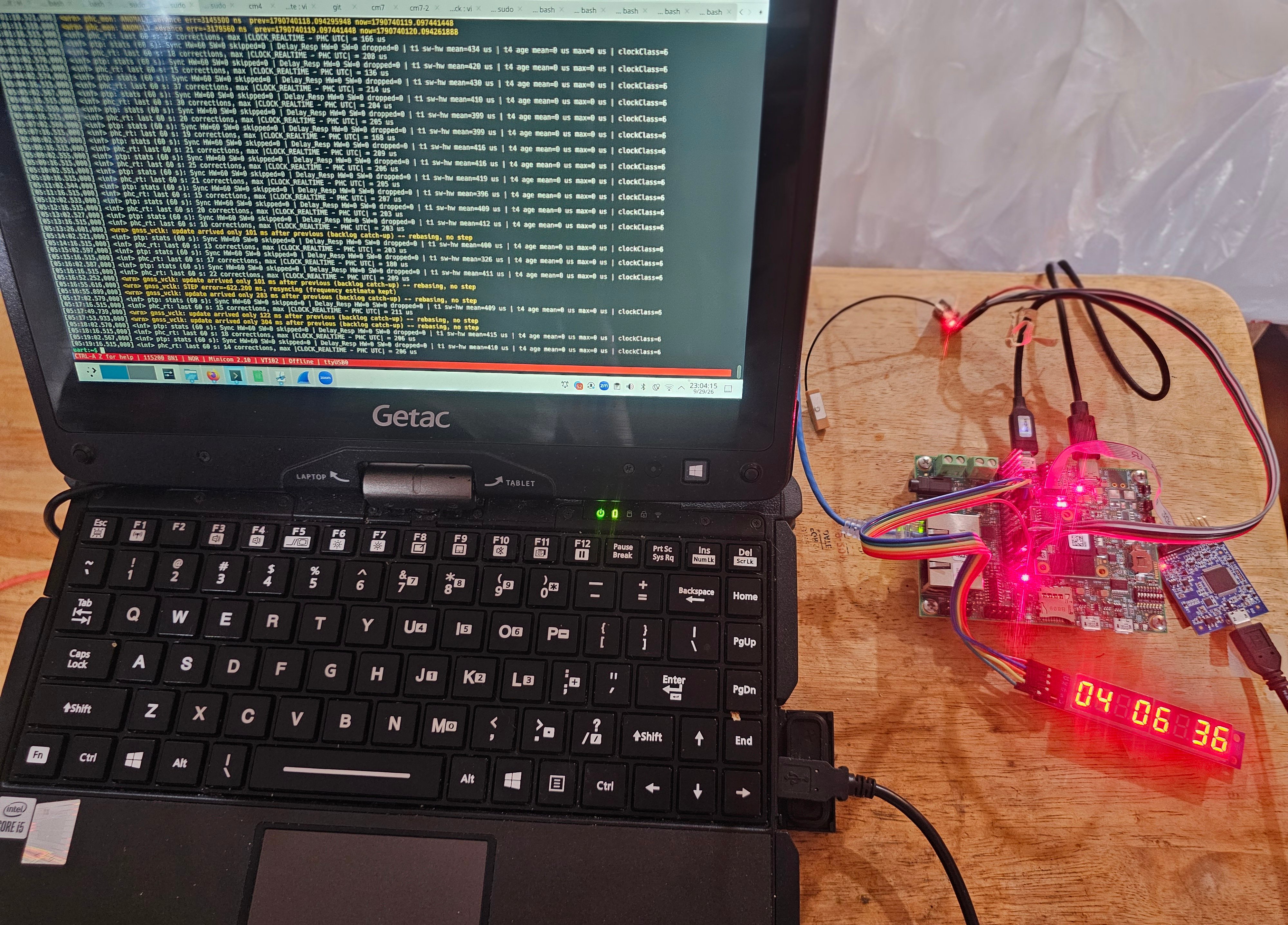
Image 2: CM7 Core Logging PPS Signal Inputs
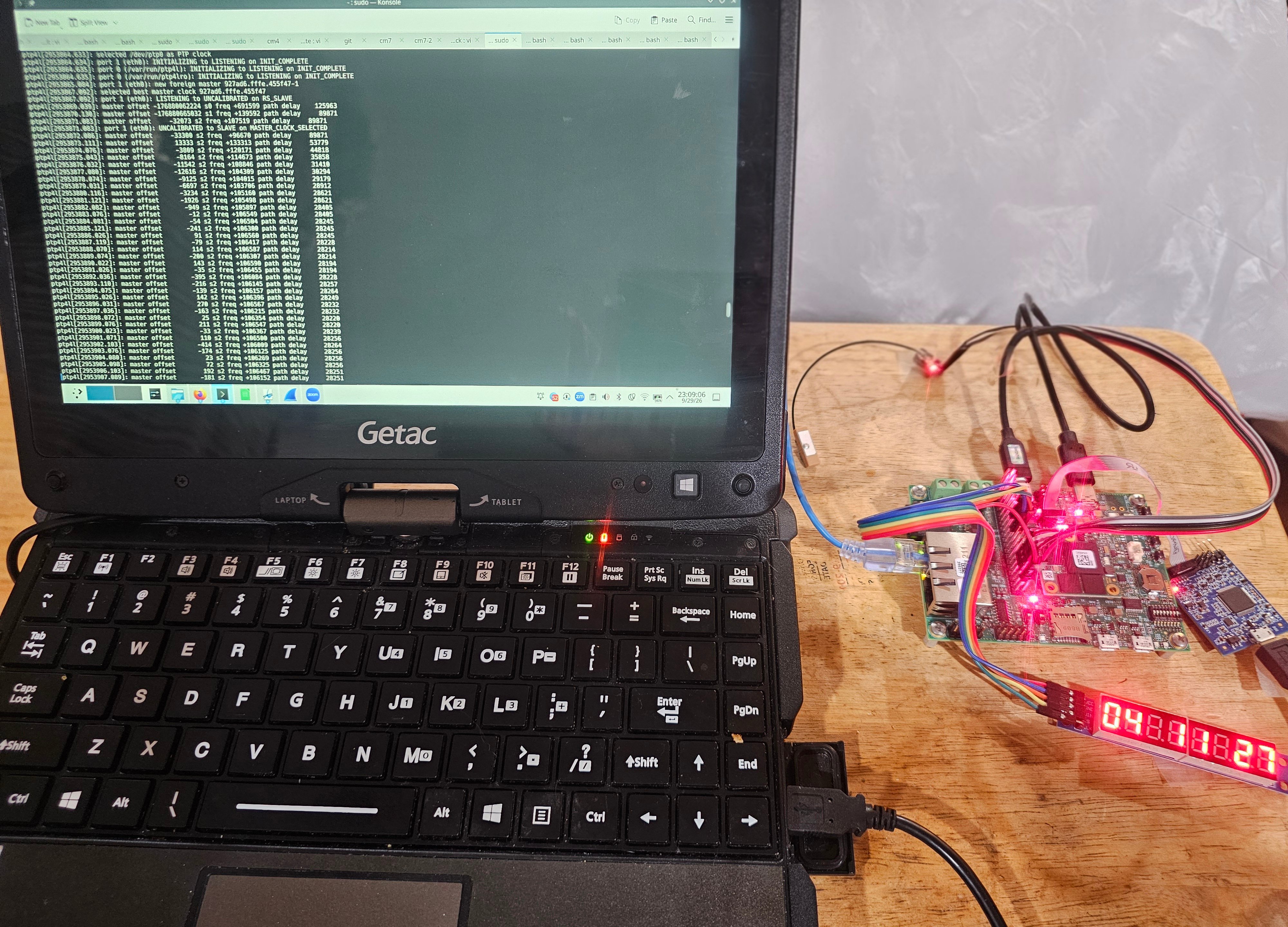
Image 3: Startup and Settling of PTP Server
Explanation of Assets
There are two key parts of the included files. The first, given the complexities of building the image and the as-of-yet unsupported pipeline, is a precompiled elf file for the Reference Software Disciplined version of the project. This can be flashed directly to the system. The second is a zip file with the Zephyr app sources to build the software version, with a key additional feature over the precompiled elf file. In the further development that lead to the hardware implementation, I realized I had not properly accounted for the leap seconds in PTP. I have gone back and patched the code to support this correctly. A good way to test if your build is successful is to flash the precompiled version, test the NTP server and PTP server (which will be 37 seconds behind). Then, compile from the source and you should find NTP and PTP in agreement.
Licensing Disclaimer
- Reference Software Implementation: Distributed under an the MIT license for educational and non-commercial validation. Additional rights may be given to Universities upon request.
- Hardware Implementation: All system firmware required for the ongoing development of the Hardware Implementation remain proprietary (All Rights Reserved).
- Commercial Inquiries: This firmware is actively maturing and arrangements have been made to deploy a hardware prototype into a production telecommunications lab for vetting against real world systems. For inquiries, please reach out here.