Learn about internal oscillators and I/O pins and how to use them with a PIC16F819, MPLAB X, and XC8.
In the previous article, we looked at how to use MPLAB X, XC8, and some hardware to program a PIC16F819. In this article, we will learn about PIC IO pins and how to use them in XC8.
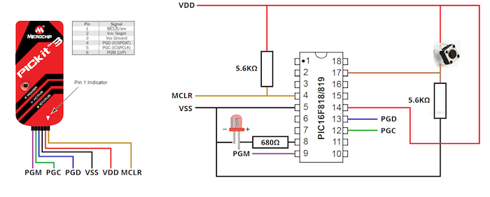
Schematic
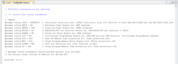
Most PIC programs will have a block of configuration code at the very top of the main.c file. Most of this will not be covered until it becomes relevant, but it is important that you put the same code (seen below) in your main.c file.
The reason for this is that the PIC has hardware (such as the watchdog timer) that can reset the device, which may cause unexpected results. Therefore, the configuration code here completely disables all of those extra features to make sure they don’t get in your way!
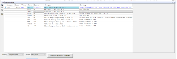
But if you are curious, you can generate your own configuration code by clicking Production > Set Configuration Bits.
This will bring up the following windows, which can be used to change bits. Once all the changes have been made, click “Generate Source Code to Output”. This will then generate code in the output window that you can copy to your main file!
Configuring the Oscillator
When we write programs in C, there are some things that we just don’t have to consider, such as how the computer will talk to the keyboard or what oscillator the CPU is using. However, microcontrollers are not the same as everyday computers, and they require some level of configuration to function correctly. So what do we need to configure to get a PIC operational? Typically, there will be two main pieces of configuration code that need to be executed before we run our main loop: oscillator configuration and I/O configuration.
PIC devices consist of many different modules, including timers, memory, and I/O peripherals, but the most important one of all is the CPU. The CPU, or central processing unit, is the circuit that actually performs operations in the form of instructions. When we create a C program for our chip to run, the compiler converts the C program into instructions that the PIC’s CPU can understand. The CPU in a PIC, like every other CPU in existence, works in discrete steps as opposed to instantaneously. To make the CPU perform these steps (which run the program), a clock source is needed. This clock source can come from an external oscillator, a crystal, or even an internal oscillator found inside the PIC itself. For the sake of circuit simplicity, most projects here will configure the PIC to use an internal oscillator.
Configuring the oscillator on a PIC chip requires us to call some specific instructions and configure specific configuration bits. This will be different depending on the PIC you use, so the code in this article will only consider the PIC16F819. The first task in our main file (created in the previous article), is to ensure that our oscillator configuration bits are set to use the internal oscillator.
PIC16F819 internal oscillator configuration
Setting this bit does not configure how fast the oscillator runs; it only tells the PIC that it will run off an internal oscillator.
The next step is to set the speed of the oscillator. Since the PIC does instructions in steps, and these steps occur on pulses from the oscillator, a faster oscillator will result in a faster PIC, which means it will be able to perform more instructions per second. But how many? PIC16 and PIC18 devices typically take four clock cycles to do an instruction, so a rule of thumb is to divide the oscillator speed by 4, and that is how fast the PIC is in instructions per second.
For example, a PIC operating at 8MHz will be able to do approximately 2 million instructions per second, and a PIC operating at 64MHz will be able to do 16 million instructions per second.
So, how do we configure the speed? This depends on each PIC, but usually, there is a register called OSCCON that can be used to adjust the speed. The best way to find out which register is involved is to look at the device datasheet under the Oscillator Configuration chapter. Below is an extract from the PIC16F819 datasheet describing the different speeds found on page 38 (PDF).
We will configure our device to run at 8MHz, and to do this we need to set IRCF to 111. In XC8, registers can be directly accessed using their name, specific bits can be accessed by using a bits and dot directive, and a group of bits (such as IRCF) can be accessed as a single value, as shown below.
OSCCON = 0b01110000 (Assigning a value to the whole OSCCON register)
OSCCONbits.IRCF = 0b111 (Assigning the three IRCF bits to 111)
OSCCONbits.IRCF0 = 1 (Assigns a binary value of 1 to IRCF0)
In our code we will use the following instruction to set the oscillator to 8MHz:
Configuring and Using I/O Ports
For our PIC to be able to interact with external circuits, it needs to be able to read and write data to its I/O pins. When dealing with I/O ports on the PIC16F819, there are three registers we need to concern ourselves with:
- TRISA and TRISB registers (direction of the pins on port A and port B)
- PORTA and PORTB registers (input and output register)
- ADCON1 register (will the pins be digital pins or analog input pins)
In most of our projects, we will be dealing with digital outputs (such as LEDs, displays, etc.), so it is important to make sure that the I/O pins are not configured as analog inputs. To ensure this, we will look at the register ADCON1 (found on page 82 (PDF)) and set the appropriate PCFG bits so that all pins associated with the ADC are digital pins.
In our circuit we have an LED output that is connected to RB2 (pin 8), so we need to configure this as an output. To do this, we use the TRIS (TRISTATE) register which is used to determine which pins are inputs and which are outputs.
Each port on a PIC can be up to 8 bits wide (RB0–RB7 for example) and each bit in a TRIS register corresponds to the output pins. If a bit is 1 (on), the following pin will be an input and if a bit is 0 (off), that bit will be an output.
For example, if TRISB equals 0, all 8 pins on PORT B will be outputs. If TRISB=255 (11111111 in binary), then all pins on PORT B are inputs. If the value of TRISB is 0xF0, which is 11110000 in binary, the first four pins in PORT B (RB0–RB3) are outputs and the last four pins (RB4–RB7) are inputs. Remember, binary numbers read from the far right first!
With this knowledge, we need to configure RB2 as an output. This can be done using the TRISB register name and accessing the TRISB2 bit as seen below.
But how do we read and write to/from I/O pins? This can be slightly different on other PICs, but on the PIC16F819 we use the PORT register, and again, we can access individual pins using the bits and dot!
Port pins are not restricted to being read at one at a time. You can instead read and write to/from the whole PORT register. This means that you can use a PORT as an 8-bit input/output port, which can be incredibly useful when interacting with devices such as alphanumeric LCD displays.
One neat feature that you may want to remember is that you can configure I/O pins whenever you want! One minute your pin could be an input pin and the next it could be an output! All that matters is that you set the correct value of the TRIS bit.
Example Program
This example program configures a PIC16F819 to read a tactile switch that is connected to its pin RA0 (pin 17) and then turn on/off an LED on RB2 (pin 8), depending on the state of the switch.
While this example may seem basic, you should now be able to program a PIC device to run your C program and read/write to the ports. This already allows you to interface with most hardware on the market, and you can start interacting with your own circuits and projects!