Use the machine learning program Wekinator to control servo motors connected through a Raspberry Pi!
In this article, part 10 of a larger machine learning series, you are going to learn to control servo motors using machine learning through the Wekinator platform. We will use processing to send the input to Wekinator. After training Wekinator, we will get the output from Wekinator through processing, and according to the output we will control the servo motors.
Catch up on the rest of the Wekinator Machine Learning series here:
Circuit Diagram
Connect the red wires of both the servos to the 5V GPIO pins of Raspberry Pi. Then connect the black wires of both the servos to the ground of Raspberry Pi. In the end, connect the yellow wire from one of the servos to the GPIO 4 of the Raspberry Pi and yellow wire from the other servo to the GPIO 17 of Raspberry Pi.
How to Run the Program
First of all, you will need to download the sketch from the quick walkthrough page of Wekinator.
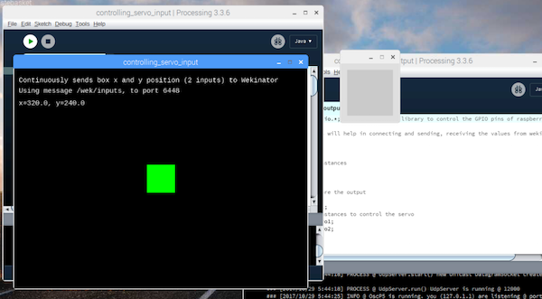
Download the on-screen mouse control example from there. Unzip it and open sketch in processing. This sketch will give the input to the Wekinator. You will need another sketch to get the output from the Wekinator. The code for that sketch is at the end of this post. Paste that into processing and run it. Both the processing output windows will look like shown below.
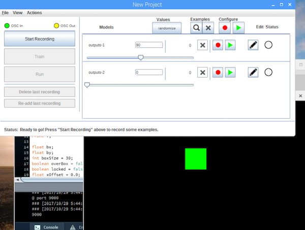
Now open the Wekinator and make the settings as shown in the below figure. Set the inputs and outputs to 2 and then set the type to “custom” and click on “configure”.
When you will click on “configure”, a new window will open up. Change the settings in that window as shown in the below figure.
Now drag the green box in the processing window to the left center side and set the settings in the Wekinator window as shown below. After that, start the recording for half a second.
Now drag the green box in the processing window to the right center side and set the settings in the Wekinator window as shown below. After that, start the recording for half a second.
Now drag the green box in the processing window to the center top and set the settings in the Wekinator window as shown below. After that, start the recording for half a second.
Now drag the green box in the processing window to the bottom center side and set the settings in the Wekinator window as shown below. After that, start the recording for half a second.
Click on “Train”, then click on “Run”. Now when you drag the green box in the processing window, the servos connected to the GPIO pins of the Raspberry Pi will move according to that.
Processing Code
import processing.io.*;  // Importing the library to control the GPIO pins of raspberry pi

// Below libraries will help in connecting and sending, receiving the values from wekinator
import oscP5.*;
import netP5.*;

// Creating the instances
OscP5 oscP5;
NetAddress dest;

// Variable to store the output
public int output;
public int output1;
// Creating the instances to control the servo
SoftwareServo servo1;
SoftwareServo servo2;

void setup()
{
  // Initializing the pins for servo
  servo1 = new SoftwareServo(this);
  servo1.attach(17);
  servo2 = new SoftwareServo(this);
  servo2.attach(4);

  // Starting the communication with wekinator. listen on port 12000, return messages on port 6448
  oscP5 = new OscP5(this, 12000);
  dest = new NetAddress("127.0.0.1", 6448);
}

// Recieve OSC messages from Wekinator
void oscEvent(OscMessage theOscMessage) {
  if (theOscMessage.checkAddrPattern("/wek/outputs") == true) {
    // Receiving the output from wekinator
    float value = theOscMessage.get(0).floatValue(); // First output
    float val = theOscMessage.get(1).floatValue();

    // Converting the output to int type
      output = int(value);
      output1 = int(val);
  }
}

void draw()
{
  if (output > 0 && output < 180)
  {
  servo1.write(output);
  }
  if (output1 > 0 && output1 < 180)
  {
  servo2.write(output1);
  }
}