Learn how to transmit MQTT messages from an ESP8266/NodeMCU to a Raspberry Pi running an MQTT broker.
In this tutorial, we will learn how to transmit MQTT messages from an ESP8266/NodeMCU to a Raspberry Pi running an MQTT broker. Our NodeMCU will read the light level via a light dependent resistor (LDR), and then transmit this information to a Raspberry Pi via MQTT over Wi-Fi.
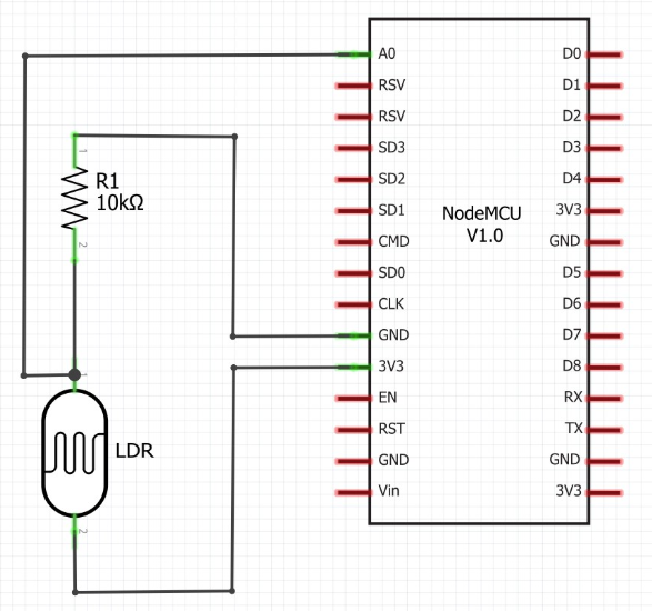
Circuit Diagram
Figure 1. Tutorial Circuit
What is MQTT?
Message Queuing Telemetry Transport (MQTT) is a messaging protocol which works on any device with an internet connection, making it one of the most commonly used protocols in IoT projects. It is designed to be used on systems which have low bandwidth restrictions, and so is ideal for home automation or any Internet of Things (IoT) application.
The advantages of MQTT include its low bandwidth, its simple implementation, and it is suited for unreliable connections.
Figure 2. MQTT-based System
MQTT requires the use of a “broker” — an application that receives and transmits MQTT messages. In this tutorial, our broker is Mosquitto, which will be installed on a Raspberry Pi. The second component of an MQTT system is a “client”, which connects to a central broker and can publish or subscribe to MQTT messages.
MQTT messages are identified by a topic, which is part of the message. In this tutorial, we will be publishing and subscribing to the “makerpro/mqtt_tutorial/light” topic.
Installing the Mosquitto Broker on a Raspberry Pi
The first step I would recommend is updating the software on your Raspberry Pi. Open up a terminal and enter the following commands:
sudo apt-get update
sudo apt-get upgrade
sudo reboot
Once your Pi has rebooted, you can install our MQTT broker Mosquitto, again in the terminal type:
sudo apt install -y mosquitto mosquitto-clients
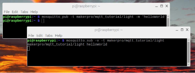
Test Mosquitto by creating two new instances of the terminal. In one terminal enter the following:
mosquitto_sub -v -t makerpro/mqtt_tutorial/light
In the other new terminal enter:
mosquitto_pub -t makerpro/mqtt_tutorial/light -m 'helloWorld'
After pressing enter on your second terminal you should see the message “makerpro/mqtt_tutorial/light helloWorld” on the first terminal as illustrated in Figure 3.
Figure 3. Raspberry Pi Mosquitto Test
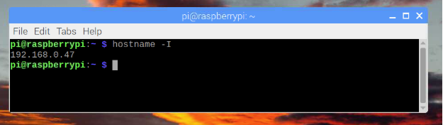
With Mosquitto successfully tested on your Raspberry Pi, you need to find its IP address by typing the command hostname -I.
This will return a number like 192.168.0.47 as shown in Figure 4. Your Pi may give you a slightly different number to this.
It is important that you write this number down somewhere safe. You will need it for the NodeMCU to connect to our Mosquitto server.
Figure 4. Raspberry Pi IP Address
Building the Circuit
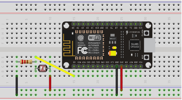
The circuit for this tutorial (as shown in Figure 5) comprises of a LDR, a 10K resistor and our NodeMCU development board.
Figure 5. Breadboard Circuit
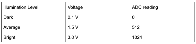
The LDR and resistor form a potential divider, where the NodeMCU’s analog input reads the voltage between them. As the LDR’s resistance changes with the illumination level, the voltage level between the LDR and the resistor changes, which is demonstrated in Table 1.
Table 1. Illumination/Voltage/ADC Levels
Installing the Arduino IDE and PubSubClient Library on Your Computer
You’ll be using the Arduino IDE to program and flash the NodeMCU development board. There are various steps required to install this before we jump into programming.
- Download and install the IDE
- Run Arduino and display the Preferences dialog from the File menu
- In the Additional Boards Manager URLs textbox paste the following text: http://arduino.esp8266.com/stable/package_esp8266com_index.json
- Click OK
- Select “Board Manager” from The Tools/board menu
- Type “esp8266” in the search box and then install “esp8266 by ESP8266 Community”,
- Select “Generic ESP8266 Module” from Tools/Board
- Open the Library Manager via Tools/Manage Libraries…
- Search for “PubSubClient” and then install PubSubClient by Nick O’Leary
Adapt and Upload the Software to the NodeMCU
First, download a copy of the software for the NodeMCU from Github.
Before uploading the code to your board, you need to makes some changes to the Wi-Fi and broker addresses at the top of the file.
const char *WIFI_NETWORK_NAME = "********";
const char *WIFI_PASSWORD = "*********";
const char *MQTT_BROKER = "192.168.0.47";
Change the WIFI_NETWORK_NAME AND WIFI_PASSWORD to your home network login details. For example, if your Wi-Fi network is called myWifi, then the top line would look like this:
const char *WIFI_NETWORK_NAME = "myWifi";
Update the variable MQTT_BROKER to the IP Address of your Raspberry Pi (which you made a note of earlier).
Implementation
It is important that your NodeMCU and your Raspberry Pi are connected to the same network. Note that if you reboot your Raspberry Pi, it may change its IP address which would mean changing the NodeMSC’s code as well.
Once booted, the software on the NodeMCU will regularly read its ADC and then send an MQTT message to the broker stored on your Raspberry Pi. The broker will then redistribute messages to any clients subscribed to that topic.
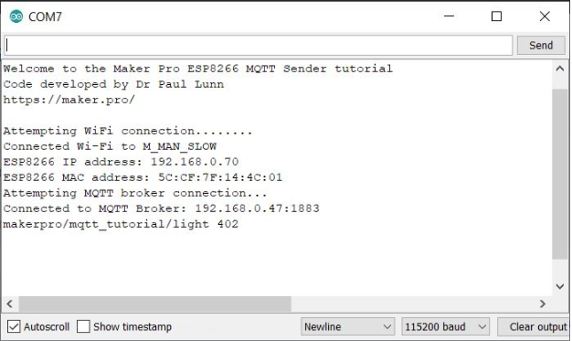
The NodeMCU code utilizes the serial port to output debugging messages. If you connect the Arduino IDE’s serial monitor you should see an output similar to the message in Figure 7.
Figure 7. Serial Output from NodeMCU
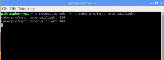
You should start receiving MQTT messages on your broker that you can confirm by opening a terminal window on your Pi and typing the following:
mosquitto_sub -v -t makerpro/mqtt_tutorial/light
This will allow you to receive regular messages in your console as in Figure 8.
Figure 8. Subscription to makerpro/mqtt_tutorial/light topic.