General Purpose Input/Output
General Purpose Input/Output is what GPIO stands for, and describes the jobs of the pins on Raspberry Pis perfectly. They are very similar to Arduino pin ports as they can be configured to either read inputs or write outputs. These pins let your Pi interact with different components such as buttons, potentiometers, and buzzers.
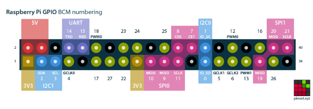
There are two naming schemes you should familiarize yourself with: WiringPi and Broadcom numbering. The latter is what each pin is officially called, displayed in green for the pins in the image above. WiringPi, the GPIO interfacing library you will most likely be using, has its own hardware-independent numbering system internally. Remember to verify which pin you are actually writing to or from when programming your Pi.
Power and Ground Pins
The power and ground pins are used to power external circuitry. All Raspberry Pis with the standard 40 GPIO pins will have two 5V pins and two 3.3V pins, always in the same place.
Along with the 5V and 3.3V pins, 8 ground pins are available. Power and ground pins are what let your Raspberry Pi power components like LEDs and motors in your project. However, remember that the proper HAT or external circuitry should always be installed before attempting to power anything through these pins. Powering something with too much current draw or significant voltage spikes, like a motor without the appropriate motor controller, will damage the pins and could render them unusable.
Alternative Functions
While many projects can get along with power and input pins, sometimes different abilities are required from a Pi. Luckily, some GPIO pins double as I2C, SPI, and UART interfaces. The Pi 4 has expanded the capability of many pins by supporting these interfaces on more of them than the Raspberry Pi 3b+ before it. Below is a brief description of each.
I2C
I2C, or the Inter-Integrated Circuit protocol, allows your Raspberry Pi to control multiple sensors and components, known as slaves. The communication is done through the SDA (data pin) and SCL (clock speed pin). Each slave device is created with a unique address to allow for fast communication with many devices. The ID_EEPROM pins are also I2C, but are used for communicating with HATs, not slave components.
SPI
SPI, or Serial Peripheral Interface, is also used to control components with a master-slave relationship, though it is not as compact. It requires clock (SCLK), Master Out Slave In, and Master In Slave out pins to function. The pins do what their names imply, with SCLK regulating data speed, MOSI used to send orders from the Pi to attached devices, and MISO doing the opposite.
UART
If you’ve tinkered with Arduino before, you may have heard of UART or Serial before. Universal Asynchronous Receiver/Transmitter is used to hook up Arduinos to the computers that program them and also for communication between other devices with the receive and transmit pins. These pins can be used to control your Pi through another computer if the serial console is enabled in raspi-config or to control an Arduino directly if you are not able to use a USB cable for your project.
PWM
Along with these functions, all pins are capable of software PWM while GPIO12, GPIO13, GPIO18, GPIO19 are capable of hardware pulse-width modulation.
Official 40-pin RPi List
While the standard pinout for all 40-pin Raspberry Pis has remained the same, you can find an updated list of pin functions for the Raspberry Pi 4 at the official raspi-gpio repository.
Find yourself constantly forgetting what pin does what? Check out the awesome Raspberry Pi B+ leaf, created by Andreas Gohr (better known as Splitbrain). His design can be printed out and placed directly on top of the board for an easy way to keep all the pins straight.
* Cover image courtesy of pinout.xyz.