Learn how to build an electronic tape measure using an HC-SR04 ultrasonic sensor and an Arduino Uno board.
Have you ever seen a robotics project with a device that looks like a pair of big cartoon eyes and wondered what that part does? Chances are you were looking at an ultrasonic sensor. In this tutorial, you will learn about the HC-SR04 ultrasonic sensor, including how to wire it with an Arduino to build an electronic tape measure.
How Does an Ultrasonic Sensor Work?
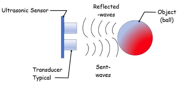
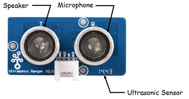
An ultrasonic sensor is a device that uses ultrasonic waves to measure an object’s distance. Ultrasonic transducers — which are the microphone and speaker tandems — send and receive ultra-high frequency sound waves to obtain an object’s distance or proximity. The ultra-high frequency sound waves are reflected from an object’s surface creating a unique echo pattern.
Figure 1. An HC-SR04 ultrasonic sensor.
Figure 2 illustrates the ultrasonic sensor’s ultra-high frequency sound waves being reflected from an object’s surface.
Figure 2. Sent and reflected waves: ultrasonic sensor basic operation.
Wiring an Ultrasonic Sensor to an Arduino Using TinkerCad Circuits
With your basic understanding of how an ultrasonic sensor works, you are now ready to wire the device to an Arduino. To explore the operation of the ultrasonic sensor, you can build a virtual functional circuit using TinkerCad Circuits.
TinkerCad Circuits is a free online circuit simulator that allows a variety of electrical and electronic circuits to be simulated prior to wiring them on a real breadboard. You can even test Arduino projects (including the code) with TinkerCad Circuits. You can gain valuable electronics knowledge through experimentation prior to committing to building your physical circuit.
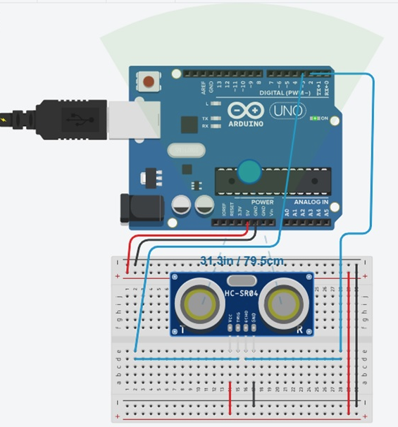
Figure 3 shows a functional ultrasonic sensor Arduino project built with TinkerCad Circuits.
Figure 3. An online ultrasonic sensor and Arduino TinkerCard Circuit.
Use Figure 4 as a reference if you have a breadboard to experiment with the ultrasonic sensor.
Figure 4. A breadboard wiring version built in TinkerCad Circuits.
Wiring an Ultrasonic Sensor With an Arduino on a Breadboard
You can use the ultrasonic sensor Arduino circuit built in TinkerCad Circuits or the electrical wiring diagram shown in Figure 5 to build your sensing device.
Figure 5. The electrical wiring diagram for an actual ultrasonic sensor to an Arduino.
If you are using a 4-pin ultrasonic sensor, the normally closed pin (NC) is wired to ground. You can place the ultrasonic sensor as shown on the breadboard and with jumper wires complete the wiring to the Arduino.
Here’s the circuit I built using a 4-wire jumper harness to wire the ultrasonic sensor to the Arduino.
Figure 6. The author's actual circuit.
The 4-wire jumper harness is color coded. Figure 7 shows the wiring connections between the Arduino and the ultrasonic sensor.
Figure 7. The 4-wire color-coded jumper wiring connections.
You have now successfully wired an ultrasonic sensor to an Arduino! You are now ready to install (upload) the ultrasonic sensor code to the Arduino.
The Ultrasonic Sensor Code
The last part of the project is uploading the ultrasonic sensor code to the Arduino. Connect the Arduino to your desktop PC or laptop computer using a USB cable. In Arduino IDE, enter the code shown below. You can also download the code to your desktop PC or laptop computer’s hard-drive. In the IDE, you can upload the code by clicking the horizontal arrow.
This sketch reads a PING))) ultrasonic rangefinder and returns the distance to the closest object in range. To do this, it sends a pulse to the sensor to initiate a reading, then listens for a pulse to return. The length of the returning pulse is proportional to the distance of the object from the sensor.
The circuit:
- +V connection of the PING))) connected to +5V
- GND connection of the PING))) connected to ground
- SIG connection of the PING))) connected to digital pin 7
Full Project Code
/* Ping))) Sensor

  */

// this constant won't change.  It's the pin number
// of the sensor's output:
const int pingPin = 7;

void setup() {
  // initialize serial communication:
  Serial.begin(9600);
}

void loop()
{
  // establish variables for duration of the ping,
  // and the distance result in inches and centimeters:
  long duration, inches, cm;

  // The PING))) is triggered by a HIGH pulse of 2 or more microseconds.
  // Give a short LOW pulse beforehand to ensure a clean HIGH pulse:
  pinMode(pingPin, OUTPUT);
  digitalWrite(pingPin, LOW);
  delayMicroseconds(2);
  digitalWrite(pingPin, HIGH);
  delayMicroseconds(2);

  digitalWrite(pingPin, LOW);

  // The same pin is used to read the signal from the PING))): a HIGH
  // pulse whose duration is the time (in microseconds) from the sending
  // of the ping to the reception of its echo off of an object.
  pinMode(pingPin, INPUT);
  duration = pulseIn(pingPin, HIGH);

  // convert the time into a distance
  inches = microsecondsToInches(duration);
  inches = inches +2;// Ultrasonic Calibration factor
  cm = microsecondsToCentimeters(duration);
  cm = cm +2; // Ultrasonic Calibration factor

  // Display measured values on the Serial Monitor
  Serial.print(inches);
  Serial.print("in, ");
  Serial.print(cm);
  Serial.print("cm");
  Serial.println();

  delay(1000);
}

long microsecondsToInches(long microseconds)
{
  // According to Parallax's datasheet for the PING))), there are
  // 73.746 microseconds per inch (i.e. sound travels at 1130 feet per
  // second).  This gives the distance travelled by the ping, outbound
  // and return, so we divide by 2 to get the distance of the obstacle.
  // See: http://www.parallax.com/dl/docs/prod/acc/28015-PING-v1.3.pdf
  return microseconds / 74 / 2;
}

// microsecondsToCentimeters function
long microsecondsToCentimeters(long microseconds)
{
  // The speed of sound is 340 m/s or 29 microseconds per centimeter.
  // The ping travels out and back, so to find the distance of the
  // object we take half of the distance travelled.
  return microseconds / 29 / 2;
}
You should immediately see distance data scrolling down in the IDE. Figure 8 shows the data of an example distance measuring session.
Figure 8. An example distance measuring session with an electronic tape measure.
Place a small scale or ruler between the ultrasonic sensor and the object from which you are measuring distance. How accurate are your readings compared to the actual distance measured?
The measurements should be very near to identical, which means you have successfully built an electronic tape measure. You can observe a variety of objects and their measured distance with your electronic tape measure. Happy measuring!
Note
This project code was originally created by David A Mellis, modified by Tom Igoe, and later modified by Don Wilcher. This example code is in the public domain.