Learn how to use Tinkercad to design, build, and test simple circuits.
Tinkercad already has a lot to offer as a design program, but it also serves as a replacement for Autodesk’s discontinued “123D Circuits” service, which was a free and easy to use breadboard simulator. This article will introduce you to the basics of Tinkercad Circuits which, like Fritzing, is a great design resource for makers.
To familiarize yourself with Tinkercad and its features, check out these other articles:
Getting Started
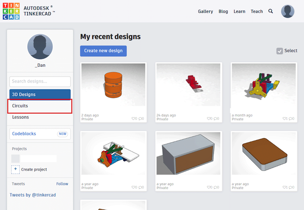
To get started, visit Tinkercad's website and create an account or log into an existing one. Then select “Circuits” on the left side of the screen:
After logging in to Tinkercad, click on "Circuits" on the left-hand side.
Select “Create new Circuit” on the next page and you’ll be greeted with the following screen:
The "Create New Circuit" homepage in Tinkercad.
To familiarize yourself with the circuit design homepage, let's go over the areas I've marked with numbers:
- Change the name of your design here
- This is the main toolbar. From the left to the right: Rotate the selected part clockwise, delete the selected part, undo and redo your last action(s), create annotations and toggle their visibility.
- Some parts allow you to change their program. Click here to do so.
- Start the simulation
- Export your design to Autodesk EAGLE.
- Choose the parts to display in the list below. I recommend choosing “All”.
- These are the parts you can use.
- The main work area. Drag and drop parts here to add them to your design.
- Fit everything into the view.
The camera can be moved by holding down any mouse button and moving your mouse without hovering a part.
Creating a Simple Circuit Design
I created a simple design which lets a user generate pseudo-random numbers between 0 and 6. Let’s implement the clock from that design!
Start by dragging a breadboard into your design and place a 555-timer IC on it:
Start by adding the 555 timer IC to your design.
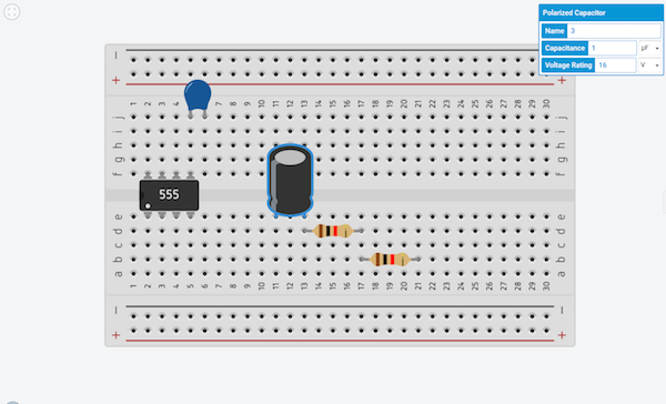
Proceed by adding the other components including:
- Two 1K resistors
- One 0.01 micro Farad capacitor
- One polarized capacitor with a capacitance of 1 microFarad
You can enter the values of each part after placing them or by clicking on a part:
Add the additional components to the circuit design.
**Hint: You can use the R-key to rotate a selected part clockwise.
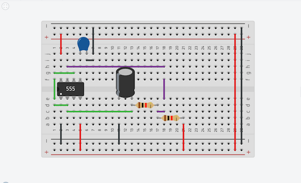
Now it’s time to connect the parts. Click anywhere to start a new connection. Click again to create an endpoint. You can change the color of the wire afterward. Connect the parts to create a simple clock:
Add connections between the components.
You can add a voltage source and an oscilloscope to test your circuit. Hit “Start simulation” to check your design:
Add a voltage source and oscilloscope to test the circuit.
You can change the oscilloscope’s settings by clicking on it.
Using the Programming Tool on Your Completed Circuit
Now that the clock is functional, let’s connect it to an Arduino and write some code. Add an Arduino to your design and connect the timer’s pin three to pin two of the Arduino.
Don’t forget to connect the ground of the Arduino to the one on the breadboard. When you are done, click the “Code” button in the top menu bar:
Click the "code" button to begin programming your build.
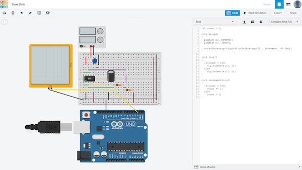
The code window will show the “blocks” editor by default. I changed it to text only by clicking the dropdown-list and selecting text. Enter the example program code (found below) and start the simulation. The LED on the Arduino should blink slowly.
int count = 0;

void setup()
{
  pinMode(13, OUTPUT);
  pinMode(10, INPUT);

  attachInterrupt(digitalPinToInterrupt(2), increment, RISING);
}

void loop()
{
  if(count > 250)
    digitalWrite(13, 1);
  else
    digitalWrite(13, 0);
}

void increment(void)
{
  if(count < 500)
    count += 1;
  else
    count = 0;
}
Next Steps
After you are done, you can export your work to Autodesk EAGLE to create a PCB design or you can generate a list of the necessary components and then build it. To display the list, click the button next to your profile picture:
Export your list by clicking the icon next to your profile picture.
Final Thoughts
This tool is very easy to use and even though it doesn’t have a large number of components to choose from, you can build simple designs and test them.
I use tools like this quite often to explain simple designs that can easily be understood without needing to know how to read a complicated circuit diagram. However, the simplicity comes at a price: you can’t build that much with it and you can’t add custom parts.