CircutScoper
- Mar 29, 2022
- 300
- Joined
- Mar 29, 2022
- Messages
- 300
THANX!!. When I am finished with the 1st pcb with the relays I will try this circuit. As hobbyist there is a lot of knowledge I am missing but on the other hand I have a lot of qulities in other fields. I think this will compensate!View attachment 55701
Of course there is! Just use a DPDT toggle switch instead of push buttons and you need zero relays.
Hello CircutScoper, Good morning. Both circuits are working fine. The 2-relay circuit which I have built and to be switched over GND is functioning without the 2 diodes (diodes on right-hand side of my diagram) I became aware that I had switched mistakenly the brown cable to the pin 1 of the 2nd relays and the black on pin 2 of the same relay. I corrected this and all is functioning as it should be.
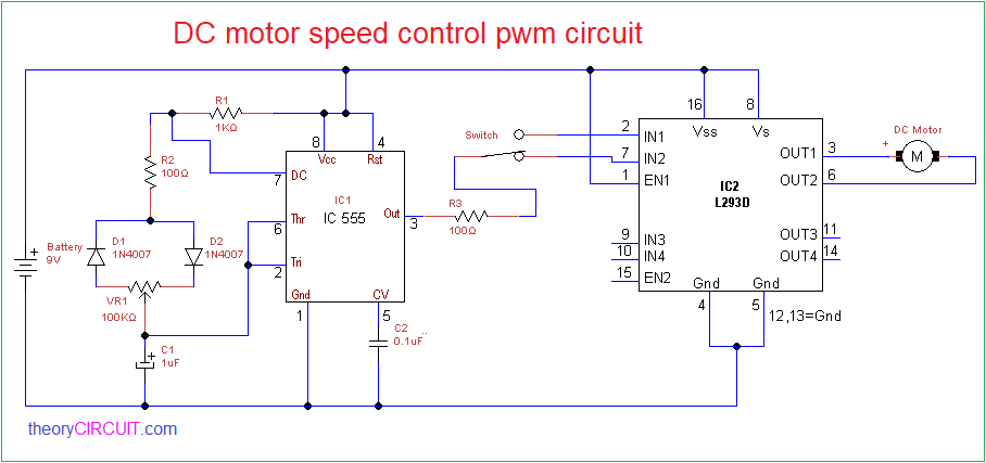
As you mentioned before, building the circuit with 2 relays is cost-expensive, I thought it should do the job using an IC such as the L293 or the CD754410. See https://nathandumont.com/blog/h-bridge-tutorial
So, I will experiment with this IC. I read an article in which was indicated that connecting a potmeter to EN1 of the IC, you could reduce speed of the motor which is running to fast in comparison with the 2nd motor.
I keep you informed about the progression
Thanx again
Greetings Harry
THANK YOUCongratulations on getting your circuits to work.
As for reducing the speed of one of the motors, you might consider a simpler solution as illustrated by D1 and D2 in the diagram below. If one diode pair didn't slow it enough, you can of course add more.
View attachment 55770
Hello CircutScoper.THANK YOU
It's possible, but you'd first need to measure the current draw of the motors to be able to estimate the resistance (R = V / I) and power rating (P = I^2 R) needed. Then, in operation, the resulting speed regulation from a rheostat would be inferior to diodes, causing a greater tendency for the motors to bog down and even stop if frictional drag varies.Hello CircutScoper.
I tried yesterday the diode circuit. It works like you have suggested. I will try the same diode circuit solution to the other side of the motor. Each diode uses approx 0.7 Volt, so totally 1,4 Volts on each side.
Is it possible to use a potentiometer ( 3 legs) or a rheostat (2 legs) in stead of diodes?
greetings
Harry
They only operate in the reverse biased mode, as soon as the motor moves off the limit, they are both closed.Hello CircutScoper.
I tried yesterday the diode circuit. It works like you have suggested. I will try the same diode circuit solution to the other side of the motor. Each diode uses approx 0.7 Volt, so totally 1,4 Volts on each side.
Is it possible to use a potentiometer ( 3 legs) or a rheostat (2 legs) in stead of diodes?
greetings
Harry
I tried both diode circuits (for left and right turn) but apparently the rpm are little less then without the diodes. So to decrease the rpms, the only solution is to lower voltage more of this specific motor, or to change the opposite motor, which is obviously slower. However this motor is turning the way I like it.They only operate in the reverse biased mode, as soon as the motor moves off the limit, they are both closed.
i.e. Producing a short across the diodes. Only Forward biased momentarily.
You're looking at the wrong diodes. Check out D1 and D2.They only operate in the reverse biased mode, as soon as the motor moves off the limit, they are both closed.
i.e. Producing a short across the diodes. Only Forward biased momentarily.
Please recall that, per my original suggestion, there remains another solution: More pairs of diodes. 7 pairs, for example, would be guaranteed to stop the motor completely, since 7 x 0.7V = 4.9V. Somewhere between the 1 you have now and that 7 is very likely to exist the speed you want.I tried both diode circuits (for left and right turn) but apparently the rpm are little less then without the diodes. So to decrease the rpms, the only solution ...
Oké, this simple and a very logic explanation. I will try this tomorrow. I am now making a circuit diagram of the circuit previously posted. I have to see the circuit in progress prior to understanding it. (I'm still a rooky and hobbyist and not an electrician)You're looking at the wrong diodes. Check out D1 and D2.
![]()
Please recall that, per my original suggestion, there remains another solution: More pairs of diodes. 7 pairs, for example, would be guaranteed to stop the motor completely, since 7 x 0.7V = 4.9V. Somewhere between the 1 you have now and that 7 is very likely to exist the speed you want.
This is the ultimate extension of the series-diode concept. It is much simpler than your 555 based circuit and your chances of successfully using it are therefore much better.Oké, this simple and a very logic explanation. I will try this tomorrow. I am now making a circuit diagram of the circuit previously posted. I have to see the circuit in progress prior to understanding it. (I'm still a rooky and hobbyist and not an electrician)
Oké, thank you. In fact I can make a separate pcb board containing the diodes in series and make on each crossing of the diodes pair a male header/jumper and using a connecting cable to the limit switch. This circuit is making it easier than using the NE555/L293.This is the ultimate extension of the series-diode concept. It is much simpler than your 555 based circuit and your chances of successfully using it are therefore much better.
Frankly, there are so many errors in the 555 schematic you drew that I won't even attempt to correct it.
View attachment 55892
Great example this diode circuit. I made the circuit this afternoon and to reduce the rpms, 5 pairs of diodes are needed to become the desired rpm. See enclosed the photo.Oké, thank you. In fact I can make a separate pcb board containing the diodes in series and make on each crossing of the diodes pair a male header/jumper and using a connecting cable to the limit switch. This circuit is making it easier than using the NE555/L293.
Can you explain to me why a potentiometer is not working in this circuit whereas a potmeter connected directly to voltage+/ground- and (whiperpole)motor is functioning.
Sorry for this question: you have already answered this in a previous post!!
I answered, but not in very good detail. Let me try again.Oké, thank you. In fact I can make a separate pcb board containing the diodes in series and make on each crossing of the diodes pair a male header/jumper and using a connecting cable to the limit switch. This circuit is making it easier than using the NE555/L293.
Can you explain to me why a potentiometer is not working in this circuit whereas a potmeter connected directly to voltage+/ground- and (whiperpole)motor is functioning.
Sorry for this question: you have already answered this in a previous post!!
Thanks for the extensive explanation and sorry for my late response. I am working at my front door which takes a lot of effort. The previous paint is floating on the base paint: the base paint is affecting the finish paint, so I have to strip the whole door and repaint it with an Alkyd base paint and then the Alkyd finish paint. I will come back in a short while. Again thanks for your cooperation. greetings Harry from a sunny .I answered, but not in very good detail. Let me try again.
1. The fundamental reason that trying to control a DC motor's speed with a resistor (or pot) is that when the mechanical friction loading a motor changes, the current drawn by the motor will also change -- increasing when friction increases and vice-versa.
2. If resistance is being used to slow the motor, these changes in current draw will cause the voltage provided to the motor to likewise change -- decreasing the voltage when friction -- and therefore current draw -- increase and vice versa.
3. Because a typical DC motor's speed tends to be proportional to applied voltage, 1 and 2 imply that the voltage changes that result from changes in friction will exaggerate friction-induced changes in speed. E.g., increased friction tends to slow a motor anyway, and therefore the decrease in voltage caused by increased current draw (through any added resistance) caused by increased friction will make the slowdown even worse.
Q.E.D. Resistance is not the best way to control motor.
Which is to say POSITIVE resistance -- the usual kind where V = IR -- isn't the best way. It's actually possible to electronically synthesize NEGATIVE resistance -- V = -IR -- and if the right amount of this kind is placed in series with a motor, the resistance of its windings can be canceled out.
This is a VERY GOOD way to control speed, and one that I've used often. But the details are beyond this discussion.
Good morning CS,This is the ultimate extension of the series-diode concept. It is much simpler than your 555 based circuit and your chances of successfully using it are therefore much better.
Frankly, there are so many errors in the 555 schematic you drew that I won't even attempt to correct it.
View attachment 55892
Congratulations!Good morning CS,
After painting my outdoor windows and doors I am finally able to pickup my hobby. I made the above circuit again and I came to the conclusion that my previous diode circuit was NOT correct. problem The reverse diodes connection . Now the new circuit is using a max of 3 diode pairs for obtaining a reduced speed. Only 1 circuit is needed whereas I said previously that 2 circuits (1 for front rotation and 1 for backward rotation) were needed. But logically the circuit is running from + to - voltage and vice versa so only 1 circuit is needed.
As for the PWM circuit containing the NE555 and the SN754410, I managed to build the circuit and it is functioning well.