Hi, I really need some help with this. So, my paper presents the principle of the 12V DC voltage to 220V AC voltage converter, based on RL-astable. A mains transformer is used in the opposite connection of the primary and secondary, where the coils of the secondary form the reactive components of the astable. I need to do analysis of the operation of circuit and simulation of the circuit.
First step is to determine theoretical frequency of oscillation of this circuit. I couldn't find anywhere this equation, so if someone knows, please can you share it with me.
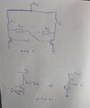
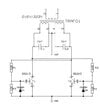
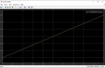
I attached below my "final circuit" (this is just principle I need to explain, but in simulation I will need some new parameters like diodes, resistors etc. and of course consumer - picture 1). Also, I will need some simulation of the output voltage (I attached below the circuit from which I need to do simulation - picture 2).
Thank you for help in advance")
First step is to determine theoretical frequency of oscillation of this circuit. I couldn't find anywhere this equation, so if someone knows, please can you share it with me.
I attached below my "final circuit" (this is just principle I need to explain, but in simulation I will need some new parameters like diodes, resistors etc. and of course consumer - picture 1). Also, I will need some simulation of the output voltage (I attached below the circuit from which I need to do simulation - picture 2).
Thank you for help in advance