Maker Pro
Maker Pro

Denon AVR 1804 amp won't switch on

73's de Edd

Aug 21, 2015
3,640
Joined
Aug 21, 2015
Messages
3,640

Looking at the schema above .
The emitter is connected to ground so it HAS to be 0 VDC.
The voltage at the base will be whatever the junction voltage results in after the voltage division of R159 and R160 are when being applied across a semiconductor base junction to ground.

Any info on the transistor collector is irrelevant, since it should be floating free and sticking out in the air.

The suspected effect now would be for the RED 3 voltage being able to flow over to RED 4 and be about the same voltage. BECAUSE an otherwise fully conducting Q151 has been taken out of that circuit by disconnecting / floating its collector lead.

73s de Edd


bushtech

Sep 13, 2016
1,025
Joined
Sep 13, 2016
Messages
1,025
Thanks St Edd

Red 3 to Red 4:
Red 3 = out leg of 7805 (IC103) = 5.6V
Flows to R158 incoming leg = 5.6V outgoing leg = 5.16V
Which is the voltage of Red 4
Looks OK to me, what am I missing ?

Must say that I'm having difficulty with readings as they jump around a lot, starting to wonder if some solder is non-conductive:confused:
 

bushtech

Sep 13, 2016
1,025
Joined
Sep 13, 2016
Messages
1,025
What I don't understand is the voltages I get on both sides of R159. It's one leg is grounded so should be zero. And I do get virtually zero on the one leg, but how does the 0.69V on the other leg come about?
 

73's de Edd

Aug 21, 2015
3,640
Joined
Aug 21, 2015
Messages
3,640
You are doing great . . .just one more test and I will explain all of that circuits function .
For this you replace the collector back to where it was connected and then lift the base so that it floats with no connection to it , just as the collector was being treated previously.
Then I am expecting the same condition of RED 4 having about that same 5.16 VDC level on it.
 

bushtech

Sep 13, 2016
1,025
Joined
Sep 13, 2016
Messages
1,025
Shame poor little transistor's head must be spinning. I'll try once more to remove it, bend it's legs without breaking them and shove it back:)
 

bushtech

Sep 13, 2016
1,025
Joined
Sep 13, 2016
Messages
1,025
Transistor survived another ordeal
Base now disconnected
R158 reads 5.61V and 5.16V on it's legs
 

73's de Edd

Aug 21, 2015
3,640
Joined
Aug 21, 2015
Messages
3,640
Yep. . . . That was exactly what was expected.
Now place that transistor base connection into place the final time . . . .lead fatigue willing.
Then another DC voltage reading from its collector to ground /emitter , to confirm what that voltage level is with that stage in full conduction, after power up.

73's de Edd

.
 

bushtech

Sep 13, 2016
1,025
Joined
Sep 13, 2016
Messages
1,025
Must say, my soldering skills have improved dramatically. Practice makes perfect I suppose.

Collector to ground = -0.15V
Collector to emitter = 0.65V
 

bushtech

Sep 13, 2016
1,025
Joined
Sep 13, 2016
Messages
1,025
Shouldn't the collector be at R158's voltage of 5.16V? Don't understand what's going on here
 

73's de Edd

Aug 21, 2015
3,640
Joined
Aug 21, 2015
Messages
3,640
Nope . . . .it's presently in saturated conduction.
Will detail that circuitry's aspects tomorrow.

73''s de Edd
 

bushtech

Sep 13, 2016
1,025
Joined
Sep 13, 2016
Messages
1,025
Thanks St Edd. Please can you tell me what the chances are that the μp is still working OK?
 

bushtech

Sep 13, 2016
1,025
Joined
Sep 13, 2016
Messages
1,025
I assume the transistor being driven into saturation is good.
Where do I go from here?
 

bushtech

Sep 13, 2016
1,025
Joined
Sep 13, 2016
Messages
1,025
Interim Report:
Well, the amp is currently running on my bench. Many many kudos to 73's de Edd for his patient off forum help to revive this patient.
After a lot of testing asked for by 73's de Edd we replaced diode D126 ( next to relay 106) which was gone. Also replaced relay 106 which was tired and damaged during previous clumsy testing. Ditto transistor Q116 which had taken a hammering. At this point the amp fired up and a reboot of the chip brought the display up and happiness.

Now need to replace the 3 secondary caps C144, C145 and C153. Especially C153 which is reading low and making IC104 (the 7805 regulator) run hot.

Then I still need to find a suitable replacement for the ICP-N15 fuse that I blew and waiting for some heatsink compound to redo all the heatsinked components including all the big transistors.

So far so good, many thanks again to 73's de Edd
 

neon128

Dec 18, 2021
1
Joined
Dec 18, 2021
Messages
1
Hello guys. Can you please guide me a little bit. I have the same amp but the sound on front left channel is weak.
I found out that i have too much Voltage on Q504FL.
All other channels have around 1.1V there. I did check all components around that, I even changed that Transistor, and the result is the same. Because of that i am getting 2 much Voltage on Q103FL, and the sound is very low and distorted. any tips where should i look for ?

Attached Files:
 

Attachments

  • denom.jpg
    denom.jpg
    176.7 KB · Views: 7
  • denom2.jpg
    denom2.jpg
    144.7 KB · Views: 6

73's de Edd

Aug 21, 2015
3,640
Joined
Aug 21, 2015
Messages
3,640
Sir neon128 . . . . .
You say . . . .
The sound on front left channel is weak.
I found out that i have too much Voltage on Q504FL.
All other channels have around 1.1V there.
Because of that i am getting 2 much Voltage on Q103FL, and the sound is very low and distorted.


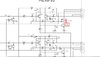
Referencing the SNIPPET below . . . . . .

The very top is just the RED boxed area that you have suspect of . . . . as being a BLOCK diagram

Let's attack this pre amp stage first . . . . . but since the Q504 collectors have DIRECT DC connection to the POWER output stage, it also could be the section with the voltage fault.

How about getting the unit operating and have an audio input so that you can hear both R and L front speakers. Then bring the front right audio up to a normal listening level . Use your balance control so that you can swing to extremes to listen to both speakers individually and then center it and keep it there. .
Connect a .1 ufd paper /or/ mylar / or / poly . . . . (NOT an Electrolytic . . .[ has DC leakage ] ) . . . . cap between the two collector connections of Q504 R and L.
Then see if the combined inputs will let GOOD sound from the RIGHT pre amp pass around the deficient LEFT pre amp.
If so, we seem to need to work with the FR pre amp section. Remove the .1 ufd cap now.

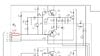
Put your metering in DC voltage measurement function and hopefully you have an auto ranging model.
I have A thru K identifiers marked in RED . . .less . . .the use of a possibly confusing l / 1.

Now do " differential " DC voltage tests between the same characters of both channels . . . . . .we are looking for the point of GREATEST voltage difference . . . as being a clue of the most suspect area.
You have mentioned the K area left channel as having 1.5 V and K area right channel as having 1.1V, so that would be a 400 mv difference.
So, check all of the other areas to see if any other area has a GREATER PROPORTIONAL PERCENTAGE of error.
You might list and return those readings.

I am the SNIPPET . . . . .
upload_2021-12-20_9-18-29.png


73's de Edd . . . . .


At our house, I have definitely done one thing differently this Christmas, I knocked over the Christmas tree and smashed all of its ornaments, just to be able to see our damn cats face . . . . . when she comes in and then realizes that, this year, I had done beat her to it !

.
 
Top