Maker Pro
Maker Pro

Digital programmable CDI ignition for 2-stroke engines

bob weir

Sep 10, 2014
235
Joined
Sep 10, 2014
Messages
235
Notice - for comments or questions please e-mail me. instead of posting a reply here.;
by keeping postings to a minimum this project will be more readable and easier
to follow along.
relevant messages from viewers will be mentioned here. with preference to those
doing an identical or similar coding and circuitry testing.

my goal is to provide everything that goes into replacing the factory analog
ignition on a 1-stroke motorcycle with a digital replacement.

such that you will be set to adapt the code and circuit to your engine

reach me at [email protected]


7-17-16
the circuit to convert the -71 deg sine lobe is shown today. its the first , positive V lobe,
the -V lobe is the -10 deg signal. the sine wave from a function generator is being used to
simulate the flywheel sensor signal . that signal works fine for testing our ADC circuits.
but wont work for the uC that is measuring the time between the + and - sine lobes.
( see the scope image on the july 11 posting )

and for a first go-around this -71 deg ADC circuit is working well.
later it will be placed in parallel with the -10 deg ADC circuit. and then we'll see how well they
play together. we need both their output pulse signals for the uC.
and then the fire-pulse out of the uC along
with the -10 deg pulse will be the 2 inputs to a TTL 7432 OR - gate. the output of which goes to the CDI circuit board to make it fire off a spark

all that will be coming up next.

and a preview ... the ADC circuits will be on their own PC board. and will follow the 2014
CDI circuit design example and use an opto-coupler to connect to the CDI circuit board.
among other things doing it this way will modular-ize the ignition system so that the same ADC board could then be connected to a 2'd CDI board. ex. one based on the UC3845 chip .
another bonus is isolating the two boards so that they do not share a common ground.


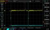
a few things to notice on the scope screen image ...
0. i messed up with the sine wave amplitude. it was suppose to be +/- 3V
and looks to be closer to +/- 4 . and possibly a little asymmetry
1. the CH 2 signal flattens out at about 1.4 V . or 2 diode V-drops . the 4148
and the Q's b-e jct combine to act like a 2*(0.7) = 1.4 zener diode clipper
2. the CH 3 pulse edges are visible and after the 7414 works them over
they are too fast to appear on the screen with the sweep rate of .010 sec/div.
this is graphic evidence of a Schmitt trigger in action
3. even tho the input sine wave goes to -4V there is no evidence in CH 3 or 4 that
it pulls those pulse signals below ground. thus no protection measures are needed
for the 7414 input pin


-71 deg ADC  july 17 001.jpg DS1Z_QuickPrint24.jpg
 
Last edited:

bob weir

Sep 10, 2014
235
Joined
Sep 10, 2014
Messages
235
july 31
the above 3 scan-images show the state of this CDI ignition project as of today

already you've seen some of the signals circuits. individually they work ok.
my efforts now are to combine them onto one board. with the uC , the new 7414 , 7432
and opto-isolator and apply the input signal and see how well they do working together

one problem seen now is using the fct. gen. sine wave as a test signal. in order to
get a 'fire' pulse out of the uC the time between the -70 and -10 pulses has to be
in its coded range of 2k to 6k RPMs.
 
Last edited:

bob weir

Sep 10, 2014
235
Joined
Sep 10, 2014
Messages
235
no , the new design signals-board circuit is not ready yet. so the old 2-Q circuit that
only works on the -10 deg sine lobe was used with the CDI board to fire the spark plug.
this was to test run the engine and hear how it sounds.

another unexpected problem has arisen. the 225 engine does fire and start. but only by giving it
squirts of starting fluid. stop the squirts and the engine dies. gas flows freely from the tank valve. my best guess is the carburator is dirty & plugged up. this calls for its removal and cleaning. a u-tube video on this topic was seen last nite. and was encouraging to see the steps, and hear his comments about this being periodic maintainance and how the engine will run better after the cleaning.

the spark was provided by the -10 deg signal from the flywheel timing coil to the 2-Q circuit and then on to the CDI board. nothing new in that. remember the engine will run ok at idle with just the -10 deg signal. it just wont speed up any.

neither n-FET has a heat sink now. they both came with one and were removed. and they both got pretty warm after only a minute run. the one i'm most concerned about overheating and
burning out is for the flyback txfr primary. as it runs at 100k Hz.

the july 4 posting has a foto of the circuit board aside the gas tank on the motorcycle . this FET is right by the black cylinder-capacitor on the left side of the CDI board. look carefully and see its 3 legs in a solderless green connector.
using it makes it easy to replace the FET as no soldering is necessary. however with that green connector there the heat sink it
was mounted to no longer fits on the board. the lack of a heat sink for that FET is likely to lead to its failure. so the plan
is to restore the FET and its heat sink the way dr tony designed them to be on the 2012
design that is my board date. for the 2014 design he changed to the 3-screw connectors for the FETs and made the heat sinks different too.

later , once i get the new signals board working with the 2012 CDI board i plan to learn
some PC board circuit software. and come up with a design that will reflect the best ideas
learned so far. including ones on dr tony's 2014 CDI board . both of his designs are general
purpose. he wrote of having plans to provide a board dedicated to a car engine. then went and died before it ever became a reality. in an e-mail he did mention a few ideas the car board would have that would be different. like having dual FETs on the primary. and of using a larger
flyback txfr. he also mused about using a uC to control the capacitor charging so it slowed
down at the top end.

every week i miss being able to write and ask him something to do with the workings of his CDI board designs. we all lost a special experimenter and reference person when he passed.
 
Last edited:

bob weir

Sep 10, 2014
235
Joined
Sep 10, 2014
Messages
235
aug 5 signals test ckt , NO uC 001.jpg
the circuit is nearly all bread-boarded. then it will be current - tested at +5V. and +12V for the opto. and if the ma numbers both look good the
fct. gen sine wave will be applied. and all 4 channels of the Rigol 1054 scope used to see what the circuit signals look like.

this is the first part of a 2-part test for the signals-board. the 2'd part will include the 12F508 uC.
so that its code can be tested . it'll pass the test if the 'fire' pulses it outputs occur at the
correct delay after the -70 deg pulse for that particular RPM.

a new idea being tried out here is using the sine-wave as-is from a fct-gen.
and not using test - pulses from another uC , the 16F506 as was done last spring.

on looking at a sinewave out of the fct . gen. on the scope screen
i saw how there would be a t-delay between sequential pulses derived from its +/- lobes.
and further thought that by vary the frequency of the sinewave out of the fct. gen
we could arrive at t-delays that mimic what the engine flywheel sensor signals provide.

cross your fingers that this idea works. if it does we've gained an unplanned but important flywheel timing signal source generator for ckt testing in the form of a plain - jane fct. gen.

a reminder note ... the 4N27 opto IC on the sketch shows identical ground symbols on its
L and R sides. they may be tied together during these bench tests. and for the testing on the
bench with the CDI ckt bd. & the 225 yamaha itself they wont be. in that case the
isolation of the opto will be utilized

and i messed up on note 1. of the sketch. between 'as' and ''ckt' is an arc-looking mark.
its shorthand for 'this'.
 
Last edited:

bob weir

Sep 10, 2014
235
Joined
Sep 10, 2014
Messages
235
DS1Z_QuickPrint28.jpg

aug 7
the circuit posted aug 5 was tested with a fct. gen. and scope. here is a screen shot from that effort.
first impression is that the 2 circuits work ok operating in parallel

to check your understanding here are some questions. often the steps that lead to success later
are small decisions just to go ahead and give something a try.

1. where in the aug 5 circuit are the probes for CH 1 , 2 , 3 and 4 ?

2. what are the +/- voltages of the sinewave when the pulse leading edges form ?

3. what is the delta-t between LE's of the CH 2,3 pulses ?

4. is the delta-t the same 10 to 70 as 70 to 10 ? account for that

5. what RPM does the 70 to 10 delta-t correspond to ? this answer is what the
uC code will come up with

6. do the pulse voltage levels all look right ?

7. later , on the motorbike , with the 2 boards each having their own separate power supply
what will it take to get all 4 of these signals on the same scope image ?

8. what frequency was the fct. gen. set to for the screen image above ?

9. do the pulses turn off at the same voltage they turned on at ?

10. what is the minimum sinewave amplitude to get both pulses ?

11. is the 7432 OR gate working correctly ?

12 . why can we see the rising & falling edges of the 4N27 opto output and not see
them on the 2 pulses that enter the OR gate ?

13. what value zener diode would you use to clip the sinewave signal from the actual
flywheel coil so that the 7414 TTL chip is not at risk from a too-big input pulse ?
 
Last edited:

bob weir

Sep 10, 2014
235
Joined
Sep 10, 2014
Messages
235
009 CARB  pilot jet aug 8.jpg aug 8
good news. the 225 engine runs.
using the CDI board for the spark. and the -10 deg signal from the flywheel.
it runs nicely. but just at idle. and i'm happy with that much

the carburator was ultrasonically cleaned and reassembled. then placed back on the engine. next the gas line connected. ( 200 ml of gas was drained out of the tank into a clear glass jar and allowed to set a half hour ... no crud settled out). then the CDI board added on too. it started right up. and , the best part, ran on its own. no squirts of starter fluid were needed to keep it spinning.

on going thru the carb lots of crud-gunk was found here'n there. mostly in the bottom bowl area.
and one critical jet was totally blocked with crud. the pilot jet.
and as this jet supplies fuel at the idle end of the RPM range it was a likely candidate for
the reason the engine would not run on its own.

i want to ride the bike some around in my yard. first tho a temporary screen needs to cover
the air intake of the carb. the 12V. battery added. and heat sinks put on the 2 CDI board FETs.

and after the urge to ride this bike is satisfied its on to finish the signals-circuit testing .
the uC is to be added to the circuit. so it is receiving
the -70 and -10 deg pulses. and sending out a fire pulse based on the timing curve.

and once it passes the indoor tests on the bench comes the test outside with the flywheel signals.

there is really a lot of work yet to do for this bike to be road-ready. including things being
overlooked presently. seems like there's always something more to do
 
Last edited:

bob weir

Sep 10, 2014
235
Joined
Sep 10, 2014
Messages
235
DS1Z_QuickPrint32.jpg

Aug 21

lets look at question 2 of the aug 7 post and learn the voltage levels of the sinewave that
trigger the -70 and -10 deg pulses.

by the screen above and BY data in upper left window you can see the -70 deg
pulse triggers 'on' when the sinewave voltage has risen to 1.00 V.

and the -70 pulse ends when the sinewave voltage drops below this same value too.

turning on and off at the same voltage is the answer to question 9.
 
Last edited:

bob weir

Sep 10, 2014
235
Joined
Sep 10, 2014
Messages
235
DS1Z_QuickPrint31.jpg

Aug 21

here is the same screen image for the -70 deg pulse in black and white.

to see how to edit the scope settings from color to b/w watch this video

 
Last edited:

bob weir

Sep 10, 2014
235
Joined
Sep 10, 2014
Messages
235
DS1Z_QuickPrint29.jpg

Aug 21

via see the BY value the -10 deg pulse triggers 'on' at about -2.2 volts and 'off' again then too

note that these 2 pulses have different voltage-trigger values and their
widths are not the same either

as the fct. gen. output signal Vp amplitude is increased from 0.5 to 1.0 then to 2.0 there are
no pulses then the -70 deg pulse appears first. then the -10 deg pulse shows up.
thus the signal from the flywheel needs to be at least 4 Vpp to get both pulses.
( this is the answer to question 10. )

Vpp = 2 x Vp

what was observed with the scope at cranking-to-start was an ampl. of 6 Vpp.
so i think we're ok. so long as it remains at that level.
 
Last edited:

bob weir

Sep 10, 2014
235
Joined
Sep 10, 2014
Messages
235
aug 24 .............. lets look at questions 3. , 4. , 5. and 8. of the aug 7 post.

3. not using the cursors , just eyeball the screen. the 70 to 10 horiz. LE distance is about 4.2 units.
............. and the timebase is 2.00ms ...... so the delta-t is 4.2x2 = .008 sec
................. the 10 to 70 distance between LE's is about 3.2x2 = .006 sec.

4. no , the delta-t's are not the same. if the pulses triggered at the same sinewave voltage then yes. ... for now i'm not making a big deal about this. if the factory analog circuitry works this way too
is not known. we'll just keep it all in mind .

5. RPM ? the code measures delta-t from the -70 LE to the -10 LE. and for this ex. it is .008 sec.
............. the code cant tell if these 2 pulses are from the fct. gen. or the flywheel. all it can do
............... is measure the delta-t between the LE's. the code as is takes this value of time
.............. to be (70-10) / 360 of the period of one flywheel revolution. thus the period is 6 x (.008) = .048 sec.
......... the Hz is then 1/.048 or about 20 . and RPM is 60 x 20 = 1200

related to this is 8. the fct. gen frequency. again one can eyeball the CH 1 signal and count
about 7 horiz. units between the 2 yellow valleys. 7 x .002 = .014 sec & 1/.014 = about 70
and on the screen can be seen 67.4 Hz in yellow

so in the aug 7 ex. the fct gen is set at 67 Hz and the code takes it to be about 20 Hz of a flywheel spin rate .

and i dunno. it just doesnt seem right. that the fct gen signal is 3.3 times the flywheel rate.
i think a review of the assembly code posted earlier this year is in order

what do you think ?

further thought and testing will verify if this analysis is correct.
 
Last edited:

bob weir

Sep 10, 2014
235
Joined
Sep 10, 2014
Messages
235
View attachment 28785.

aug 26
engine RPM at idle factory spec' ... see it there in the box ... bottom line.

this information is good to have. when the engine was running 2 weeks ago
the scope was not used. an oversight. it is now important to know what is
the upper limit in RPM the engine will idle at with just the -10 deg timing.

after reviewing some of the uC code and the math behind it some
issues have arisen. in short the RPM ranges are too big as coded.
the worst one was at idle with a range from 1200 to 1800 RPM.
the problem is that only one delay value can be coded for any range.
and it will be too early or too late for most of the particular
speeds the engine is running at in that range.

i think the remedy is to make the ranges small. recall the factory timing
chart. and how it is not a single line but a band of lines. thus for each
degree of advance on the y-axis there is a range of RPMs for that value.

go to p. 5 and see the chart on the feb 25 or mar 6 '16 post. look at -15 deg.
and see how the x-axis RPM covers from about 2600 to 3000 RPM. now that is
a range size of 400 and still seems too large. i had in mind ranges of 50-100 RPM.
fortunately we have the space in memory for all the extra code this will take.

this whole matter is the focus of my efforts at present. with 1'st getting the engine
started at idle again . with the scope this time. and capturing a few screens.

one code-saving move would be to manually set the idle
as close as can be to 2000 RPM. and , who knows, the timing error issue may
be less of a problem at higher rev's than it is at idle.

upload_2016-8-26_18-38-1.png
 
Last edited:

bob weir

Sep 10, 2014
235
Joined
Sep 10, 2014
Messages
235
JP 1 & JP 3 closed.jpg JP 1 & JP 4 closed.jpg aug 29
............... this post concerns a big timing error if the 2012 CDI design is not set up right.
there are 4 jumpers on that circuit.
remember the circuit can make a spark using its own on-board pulser signal.
or use a pulse from the outside world to make a spark.

this 2'd case is what we are doing sending a flywheel signal to the CDI ckt.
and if we jumper it wrong the fire signal to the plug is late , very late.

................. for the case of fire the spark plug with an external signal.
JP1 is to be closed and either of JP3 or JP4 is to be closed.
the question before us is which of jp3 or jp4 to close.
and what difference does it make.

these 2 screen images show what the difference is.
now either jumper 3 or 4 will lead to a spark.
the difference is about 4 x .005 sec = .020 sec.
this difference is the CH 2 pulse width. a value that changes with RPM

one CH 3 pulse provides the needed spark. one that is on time.
and the other CH 3 pulse is a very late spark and the engine wont run.

choosing jp3 means we fire on the falling edge of CH 2.

and this is what we want. doing so will keep us coordinated with making
our timing reference be the -70 deg pulse edge that arises when the
sine = wave gets to about 1.0 volts. see the aug 21 post images

CH 1 is the sinewave input from the fct. gen.
............... since we see the neg' lobe we are looking at the simulated -10 deg signal

CH 2 is U2:1 ... the -10 deg signal after the 2-Q circuit makes the neg sine lobe a pulse
.......... also since the pulse sides are visible you know its an input to U1

CH 3 is U2:8 the 200 uS pulse that triggers U1 to switch on Q1 and cause a spark

the foto with the CH 3 pulse below the rising edge of CH 2 has jp1 and jp 4 closed
... and is the setup not wanted

the other image , the one that has the CH 3 pulse below the CH 2 falling edge
has jp 1 and jp 3 closed.

getting straight about this setup can be tricky to follow. it came up as i was preparing
to re-connect the CDI board & the 2-Q ckt to the motorcycle. i'd forgot what the jp3 / jp4
difference was . so indoors both settings were scoped. and it was a good thing i did.
or the engine never would of started.
and a get-what-i-dont-want moment was avoided. since it started right up last time i tried.

this situation arises from the circuit design. the author made it so that the incoming
fire pulse signal could be active on a falling or a rising edge. the user just has to select
jp3 or jp4 according to their needs

.... also a note here about the scope screen image... the 3 signals are of different
time scales, with CH 3 being the fastest. some fooling with the horiz time base and
the trig and the scroll knob was done to get 'em presentable enough to post
 
Last edited:

bob weir

Sep 10, 2014
235
Joined
Sep 10, 2014
Messages
235
aug 30
................. in regards to the posting yesterday aug 29 with its scope screen shots ...
for those of you wondering where the CH 3 pulse with 200uS width comes from ...
it comes from the CH 2 pulse. after its passed thru the C16-R17 differentiator.
so a pulse of about .020 sec of width gets trimmed to 200uS by this C-R diff'r.

...... 200 uS was chosen as the amount of time for Q1 to be switched on
by the mosfet driver U1. the gate of Q1 needs on the order of amperes of
charge to open the drain-source channel. like lickety split fast too.
so a special device like U1 is needed here.

................. and 200 uS is plenty of time for C2 to empty its stored charge thru Q1 and into the
primary of the ignition coil. this can be easily seen with the scope.
the safest signal is not the C2 + pin. its at 250 to 300 V.
for the sake of keeping high-voltage off of your scope probe.
( unless you have shelled out the big bucks for special hi-V probes )
a safer signal with the same info is the feedback signal to U3:2
.... its only a few volts

later on with the uC in operation it will output a coded 'fire' pulse with
200uS of width. or wider . as it too will pass thru the C-R diff'r and be trimmed.

and while you are looking at the 2012 CDI circuit notice something else.
when C2 drains its charge, first thru Q1 , this then is followed by it flowing to the
ground plane of copper on the PC-board. and then it passes on into the ignition
coil primary. and out the coil's other end and back to C2.

...... i dont know what to make of all that charge flowing into the ground plane of
copper. wouldnt it spread out and raise the potential of that metal , like what happens when
a capacitor gets charged up. and thus mess with the Vcc-GND 12V. spread for
all the IC's on the board ? possibly even damaging them.

..... and yet this does not happen. the proof is the circuit continuing to work.
despite what one might think.

.......... clearly this ( dumping 30mj of C2's charge onto the ground plane on its way to a load )
as a way of doing things is an area where further knowledge is called for.
 
Last edited:

bob weir

Sep 10, 2014
235
Joined
Sep 10, 2014
Messages
235
DS1Z_QuickPrint41.jpg
sept 1
........... i think a warning is in order for these posts you have been faithfully following.
something like : 'believe what you read and see at your own risk'.
or something to remind you that 'to err is human' . or another way to spin it all
is that what we believe to be true is subject to change. depending on further thought, experience and new information.

in short ... i make many mistakes and mis-interpretations. and post them as though
there is no uncertainty. be aware of this. and that you may catch an error before i do.

truth ... this has been happened at my end here all along.
and it has me thinking many of you may have been misled most recently by the aug 29 post.
this is on the matter of jumpering the cdi board so it fires on the first CH 2 falling edge.
and how the width of the CH 2 pulse makes for a big and late timing delay to fire the plug

since then i have re-run the engine to scope the timing & fire signals .
for the purpose of learning what the idle RPMs are.
by this screen image above you can see the the CH 2 pulse is based on a relatively narrow
flywheel '-' sine lobe signal. and the delay doesnt look anywhere near the .020 of aug 29.
this is saying the fct. gen. sine wave simulated signal was not realistic in terms of
pulse width. its value is more in being able to create accurate timing between the
derived -70 LE pulse and the -10 LE pulse.

also see the bottom line on the screen. the no's in yellow and blue. you can do the
math of (30 Hz) x 60 = 1800 RPM . this is a little outside of the above image of
1300 - 1500 RPM as the idle range to set the carb to.
 
Last edited:

bob weir

Sep 10, 2014
235
Joined
Sep 10, 2014
Messages
235
sept 1
....................the attached image below followed the one above by increasing the idle.
just rotate a screw on the carb to adjust the engine idle speed up or down
the Hz reads 35 for RPMs = 2100.

..............by the graph of 'deg-advance vas RPM' you can see that 2100 is at the
upper limit of what the engine spins at with the fixed -10 deg pulse signal
derived from the flywheel sine wave

to get the engine to spin faster more timing advance is needed.
that is the job of the12F508 uC.
and coding it with many new and recent ideas is next.

..............one plan is to code in RPM ranges of 100 wide. beginning at 1500.
and base the delay to fire on
the RPM value at the middle of that range. also i plan to code just up to 2500 RPM .
and then test how well that worked. getting out of 1'st gear will be a strong
indication that we are on a better path than ever.

.... also think what it will tell us to compare the coded fire pulse timing to the
-10 deg pulse. we'll have them both . and ideally they should occur together.
from 1500 to 2000 that is. faster than that the fire pulse will happen sooner.

............. i have not ridden the bike yet. the side panel to which the circuit boards are fastened
needs re-designed. :
.......... 1. its not big enough for the new signals-bd-bd.
.......... 2. its all too close to the muffler heat.
 

Attachments

  • DS1Z_QuickPrint43.jpg
    DS1Z_QuickPrint43.jpg
    71.9 KB · Views: 113
Last edited:

bob weir

Sep 10, 2014
235
Joined
Sep 10, 2014
Messages
235
006.JPG

Sept 25
foto of new side panel and the old one. the 6" x 3" bread-board shown on the new panel holds
the A/D circuitry. i.e. the input is the flywheel timing signal sine waves. and its output goes to the
opto-isolator chip. and then its output pulse passes onto the CDI circuit board.

the horiz. part of the new panel will support the 2 battery packs. and block them both
from the heat of the engine muffler.

the A/D circuit draws around .005 amp. so small 2/3-AA Nimh batteries at 5V work ok.
and the CDI ckt. bd. uses 1-2 amp at 12V thus a 3S1P Lipo 1300mah pack is used for it.

what you are seeing is a preliminary stage in the layout of the new panel. when it is
in final form a foto will be posted here. for instance i'd like to move the black ignition coil
further away from the CDI bd and closer to the spark plug
 
Last edited:
Top