Maker Pro
Maker Pro

Fast, high current switching

dilbert9

Apr 27, 2012
34
Joined
Apr 27, 2012
Messages
34
Hello Guys. I am working on a fuel pump project. The fuel pump works like a solenoid. It needs to be switched on and off frequently in order to pump the fuel. I plan to use an Arduino to handle the switching frequency, but I am having trouble coming up with a switch device. here is the low down.

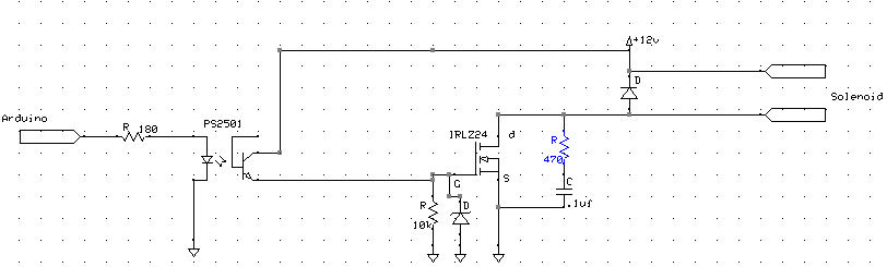
The pump runs off of 12V and uses between 1.5 and 2A when powered. The normal 3906 transistor just won't cut it. I thought about a mechanical relay, but am afraid it won't be able to switch fast enough. I was looking at this circuit:

image1.gif


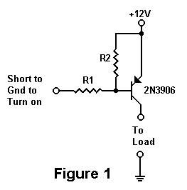
Again the problem is the transistor can't handle the current I need to supply. I am hoping someone will have some suggestions. Maybe a mechanical relay will be able to do it. I am not sure. Just hoping I could get some insight.

Thanks in advance..
 

Fish4Fun

So long, and Thanks for all the Fish!
Aug 27, 2013
481
Joined
Aug 27, 2013
Messages
481
A 5V turn on Mosfet like the IRLZ24 // IRLZ34 // IRLZ44 will provide an easy interface to your Arduino. In your diagram above, simply connect 1 side of the solenoid to +12V, move the mosfet drain to to the load side, the mosfet source to ground, eliminate R2 and choose a ~10ohm Resistor for the Gate. I also would strongly recommend a diode across the solenoid to reduce voltage spikes on turn-off.

You might also consider using an opto-coupler to drive the mosfet.

Fish
 

dilbert9

Apr 27, 2012
34
Joined
Apr 27, 2012
Messages
34
Thanks for the quick reply. Do you have a recommendation on an opto-coupler? I assume you are talking about putting that on the gate side for turn on?

Thanks once again.
 

Fish4Fun

So long, and Thanks for all the Fish!
Aug 27, 2013
481
Joined
Aug 27, 2013
Messages
481
While virtually any transistor optocoupler can be configured to work (PS2501 will work just fine, see: http://hobbybotics.com/projects/hobbybotics-optoisolated-relay-controller/ ), If you are going to source one specifically for this project, you might consider this: VO3150A. It is designed specifically for driving mosfets and IGBTs, but you really don't need anything this fancy.

Fish
 

dilbert9

Apr 27, 2012
34
Joined
Apr 27, 2012
Messages
34
Perfect!! I will order some parts tonight and see how it all works out.

Thanks once again for your help.
 

dilbert9

Apr 27, 2012
34
Joined
Apr 27, 2012
Messages
34
Hey Fish. I know this has been a while since this was posted, but I finally had time to look at this again and start working on it. After re-reading everything and looking everything up again this is what I came up with. Is this what you were talking about?

fuel-pump.jpg


Please excuse the incorrect symbols for the optocoupler as I could not find the correct one.
 

(*steve*)

¡sǝpodᴉʇuɐ ǝɥʇ ɹɐǝɥd
Moderator
Jan 21, 2010
25,510
Joined
Jan 21, 2010
Messages
25,510
In addition to this you need a resistor (about 10k) between the mosfet's gate and source to ensure it turns off

edit: Oh, and you also need a resistor to limit the current from the arduino. Around 180 ohms should be right.
 
Last edited:

dilbert9

Apr 27, 2012
34
Joined
Apr 27, 2012
Messages
34
I appreciate the reply Steve. I have made those changes here:

fuel-pump-edit.jpg


In addition to the diode across the solenoid should I be putting an additional zener diode near the mosfet? I was doing some reading and found others were doing this to add protection to the mosfet. Another reason they were using the zener was to protect the output pins of the Arduino but since I am using the optoisolator I shouldn't have to worry about this correct?
 

kpatz

Feb 24, 2014
334
Joined
Feb 24, 2014
Messages
334
The 10K resistor goes between the gate and the source (ground), not to 12V. The way you show it the FET will always be on, not what you want. Its purpose is to discharge the gate charge when the optocoupler turns off, so the FET turns off as well.

You may not need the 10-ohm resistor. It will slow down the switching time a tad, causing the FET to dissipate more heat.

The zener you mentioned would go between the gate and source (in parallel with the 10k resistor), to protect the gate from voltage surges (load dumps) which in a car can be 60+ volts, while most FETs have a max Vgs of around 20V. A 10-15 volt zener should be fine, just keep it well below the max Vgs of the FET you're using.

You should also consider a snubber circuit between the drain and source of the FET to absorb transients that slip past the flyback diode. A zener could be used, but most snubbers are simply a capacitor and resistor in series. 0.1uf and 470 ohms should work, or google "snubber circuits" for more information.
 
Last edited:

dilbert9

Apr 27, 2012
34
Joined
Apr 27, 2012
Messages
34
Wow people are replying quick today. Thanks a ton kpatz. I have fixed my schematic:

fuel-pump-edit2.jpg


I removed the resistor from the gate. I plan to order the parts tonight so just trying to make sure I have everything laid out as it should be.

Thanks again guys!!
 

dilbert9

Apr 27, 2012
34
Joined
Apr 27, 2012
Messages
34
kpatz I just noticed I missed the end of your post there about the snubber circuit. I looked it up and here is what I have:

fuel-pump-edit3.jpg


I noticed some people putting a diode in parallel with the 470ohm resistor. Is this just an additional precaution?

Here is the example I saw:

snubber-circuit.png


Again I appreciate all the help guys.
 

(*steve*)

¡sǝpodᴉʇuɐ ǝɥʇ ɹɐǝɥd
Moderator
Jan 21, 2010
25,510
Joined
Jan 21, 2010
Messages
25,510
I recommend the gate resistor as it will limit current through the zener. Without it, you would probably kill the optocoupler if you get a large enough voltage spike.

remember that the opto will probably only permit a relatively low current, so a 100 to 270 ohm resistor would be fine.

Remember you're using a 10k resistor to turn the mosfet off, so the dissipation during turn on will not be the limiting factor.

Just how often is this turned on and off? (many times per second, or every several seconds, or...?)
 

(*steve*)

¡sǝpodᴉʇuɐ ǝɥʇ ɹɐǝɥd
Moderator
Jan 21, 2010
25,510
Joined
Jan 21, 2010
Messages
25,510
OK, let's say 2A continuous, 10A on startup, and switching 5 times per second with a near 100% duty cycle (to maximise power dissipation).

I'm going from this datasheet: http://www.vishay.com/docs/91326/sihlz24.pdf

The RDS(on) is 0.1 ohms.

The dissipation whilst on is 2 * 2 * 0.1 = 0.4W. During the startup surge, the dissipation would be 10 * 10 * 0.1 = 10W

The gate charge required is 20nC. If we assume the turnoff current is through the 10k resistor and averages about 500uA. Thus it takes about 40us to turn the mosfet off. The total energy lost in each switch off event is 2 * 12 * 0.00004 / 2 = 0.48mJ, this happens 5 times in each second, so the power lost is 2.4mJ per second, or 2.4mW.

The same gate charge (20nC) mist be charged (let's say at an average of 10mA) whist the current climbs to 10A (peak current on startup). This time it takes 2uS to turn it on, and the total energy lost per event is 10 * 12 * 0.000002 / 2 = 0.12mJ, happening 5 times per second averages 0.6mW.

So the switching losses are about 3mW, totally insignificant in terms of something between 0.4W and 10W (probably averaging under 1W)

I think you're probably good to go assuming a dissipation around 1W.
 

dilbert9

Apr 27, 2012
34
Joined
Apr 27, 2012
Messages
34
So then I should be safe using the 100 - 270 ohm resistor on the gate without slowing down the switching? Or are you saying I should be safe leaving the resistor out? That was a massive amount of math and theory in a short period of time haha. I am still basically a beginner in all of this. While I have pretty good knowledge on most of this there is some theory and actual real life experience to be had.

Thanks once again!
 

(*steve*)

¡sǝpodᴉʇuɐ ǝɥʇ ɹɐǝɥd
Moderator
Jan 21, 2010
25,510
Joined
Jan 21, 2010
Messages
25,510
A 270 ohm resistor would be a good idea :)
 

dilbert9

Apr 27, 2012
34
Joined
Apr 27, 2012
Messages
34
Thanks Steve! I appreciate the help. I will order the parts today and start building.
 

dilbert9

Apr 27, 2012
34
Joined
Apr 27, 2012
Messages
34
I guess one thing I overlooked throughout this entire project is the power source for the Arduino. I plan to use the ATMega328 in a standalone format with the Arduino bootloader on the chip. I had planned to power this from the bike itself (this fuel pump is going on a bike). It uses a normal 12v battery just as any other motorcycle does. I will have it connected through the ignition switch.

What considerations do I need to take with that? I assume I will need some kind of protection circuit for the arduino to protect it from power surges from the bike.
 

dilbert9

Apr 27, 2012
34
Joined
Apr 27, 2012
Messages
34
Steve, After reading over the datasheet that you linked above I am seeing a maximum gate voltage of the FET to be 10V? Does that mean I should be using the Arduino voltage to turn on the FET instead of the 12v? As the circuit is setup it is using the 12v to turn on the FET. Here is the most recent schematic I created:


I am thinking that the 12v will be too much for the gate voltage.
 
Top